Structure for trailing edge slat of thin-airfoil-profile aircraft and linkage method of structure

A trailing edge and slat technology, applied in aircraft parts, aircraft control, wing adjustment, etc., to improve aerodynamic performance and improve aerodynamic characteristics

Inactive Publication Date: 2015-06-10
贵州贵飞飞机设计研究院有限公司
View PDF9 Cites 7 Cited by
  • Summary
  • Abstract
  • Description
  • Claims
  • Application Information

AI Technical Summary

Problems solved by technology

Therefore, when the internal space of the wing of a small thin-winged aircraft is compact, and the requirements for the shape are high, the existing structure of the trailing edge slat can no longer meet the requirements of use, and another kind of structure is required. A new trailing edge slat drive system that does not protrude from the airfoil

Method used


Image

  • Structure for trailing edge slat of thin-airfoil-profile aircraft and linkage method of structure
  • Structure for trailing edge slat of thin-airfoil-profile aircraft and linkage method of structure
  • Structure for trailing edge slat of thin-airfoil-profile aircraft and linkage method of structure

Examples


Embodiment Construction

[0016] The present invention will be further described in detail below in conjunction with the accompanying drawings and embodiments, but not as any limitation to the present invention.

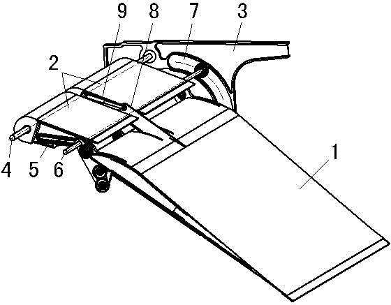
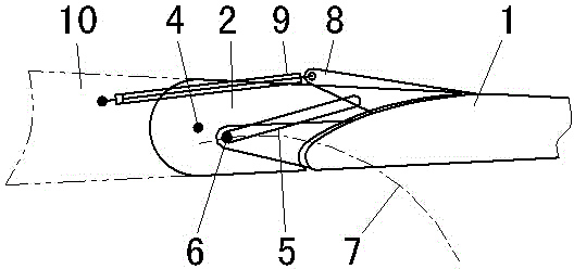
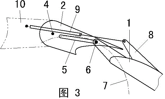
[0017] The structure of the trailing edge slat of a kind of thin airfoil type aircraft of the present invention is, the structure schematic diagram of this structure is as figure 1 As shown, the trailing edge slat of the structure of the thin airfoil aircraft trailing edge slat includes main wing 1 and sub-wing 2; In the structure diagram, only one flap slide rail 3 on the right side is drawn, and the two flap slide rails 3 are provided with sub-wing shaft holes, and the sub-wing shaft 4 passes through the sub-wing shaft holes and is rotationally connected with the front ends of the two sub-wings 2 The main wing rotation pin slip ring 5 is provided in the sub-wing 2, and the front end of the main wing 1 is connected with the main wing rotation pin slip ring 5 through the main wing rotati...


PUM


Abstract

The invention discloses a structure for a trailing edge slat of a thin-airfoil-profile aircraft and a linkage method of the structure. The trailing edge slat comprises a main foil and two sub-foils, wherein two flap runners are symmetrically arranged at the two sides of the trailing edge slat, sub-foil rotating shaft holes are respectively formed in the two flap runners, and a sub-foil rotating shaft penetrates through the sub-foil rotating shaft holes and is rotatably connected with the front ends of the two sub-foils; main foil rotation pin slide rings are arranged in the sub-foils, and the front end of the main foil is in sliding and rotating connection with the main foil rotation pin slide rings through a main foil rotation pin; the two ends of the main foil rotation pin are in sliding connection with arc-shaped main foil sliding grooves in the flap runners; a driving lug which is located at a joint gap of the two sub-foils is arranged at the front end of the main foil and is hinged to a telescopic rod which is located on an actuating cylinder between the two sub-foils, and a cylinder body of the actuating cylinder is hinged to an airfoil. According to the structure for the trailing edge slat of the thin-airfoil aircraft and the linkage method of the structure, the linkage of the main foil and the sub-foils in the trailing edge slat is realized through one actuating cylinder, the whole mechanism can be completely hidden in the airfoil of the trailing edge slat, and the smoothness of the appearance of the whole trailing edge slat is ensured, so that the aerodynamic characteristics of the trailing edge slat are improved.

Description

technical field [0001] The invention relates to a structure and a linkage method of a trailing edge slat of a thin-wing aircraft, belonging to the technical field of aircraft wing drive. Background technique [0002] Trailing edge slats are widely used in civil aviation airliners due to their better aerodynamic characteristics. For aircrafts with thin-winged wings, due to the limitation of airfoil height, the driving system of trailing edge slats on civil aviation airliners has to be transplanted. On a thin-wing aircraft, it is inevitable to arrange a large fairing on the lower surface of the wing, which seriously affects the aerodynamic performance and offsets the aerodynamic advantage of the trailing edge slat. Therefore, when the internal space of the wing of a small thin-winged aircraft is compact, and the requirements for the shape are high, the existing structure of the trailing edge slat can no longer meet the requirements of use, and another kind of structure is requ...

Claims


Application Information

Patent Timeline
Patent Type & Authority Applications(China)
IPC IPC(8): B64C3/50B64C9/16
Inventor 曾俊王焜赵荣赵天碧
Owner 贵州贵飞飞机设计研究院有限公司
Why Eureka
Try Eureka