Filling valve

A filling valve and valve body technology, applied in packaging, bottle filling, liquid bottling, etc., can solve the problems of inconvenient production and processing of parts, high processing difficulty, high production cost, etc., achieve simple structure, eliminate influence, and facilitate production Effect

Active Publication Date: 2015-06-10
HANGZHOU ZHONGYA MACHINERY CO LTD
View PDF8 Cites 2 Cited by
  • Summary
  • Abstract
  • Description
  • Claims
  • Application Information

AI Technical Summary

Problems solved by technology

Although this structure can achieve the effect of avoiding the generation of air bubbles in the container, due to the lack of structural design, the production and processing of parts is inconvenient and the production cost is high. Diversion chambers that become smaller from the inside to the outside" These two structures are difficult to process

Method used


Image

  • Filling valve
  • Filling valve

Examples


Embodiment Construction

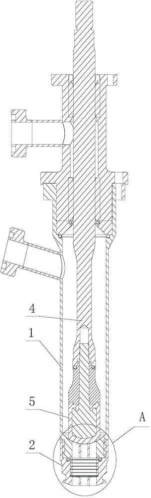
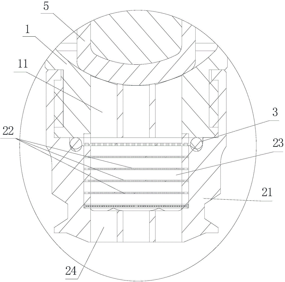
[0017] Such as figure 1 and 2 Shown is an embodiment of a filling valve of the present invention, the filling valve includes a valve body 1, a plugging rod 4 is arranged in the inner cavity of the valve body 1, a necking portion is provided at the bottom of the inner cavity of the valve body 1, the valve body 1. The bottom end forms a liquid outlet below the necking part. The liquid outlet has a liquid outlet channel 11. The bottom end of the blocking rod 4 is installed with a sealing assembly 5. When the blocking rod 4 moves up and down relative to the valve body, the sealing assembly 5 presses on or Leave the necking part to complete the switching action of the filling valve.

[0018] In this embodiment, the liquid outlet channel 11 is a honeycomb structure composed of a number of shunt holes 11, and the liquid outlet end of the valve body 1 is equipped with an anti-leakage assembly 2, and the anti-leakage assembly 2 includes a Shrink sleeve 21, the shrink sleeve 21 is fix...


PUM


Abstract

The invention provides a filling valve. The filling valve mainly comprises a valve body, wherein the valve body is provided with a liquid drain end, a liquid drain channel is formed in the liquid drain end, a liquid-leakage-preventing assembly is mounted at the liquid drain end and comprises a tightening sleeve connected with the valve body, a liquid drain part is arranged at one end, far away from the valve body, of the tightening sleeve, a plurality of drain holes are formed in the liquid drain part, the liquid drain part drains a liquid via the liquid drain holes, a mounting hole is formed in the tightening sleeve and between the liquid drain part of the tightening sleeve and the liquid drain end of the valve body, the liquid drain channel, the mounting hole and the drain holes are sequentially communicated, multiple layers of foam-removing grids with meshes are arranged in the mounting hole, the foam-removing grids are sequentially arranged in the extension direction from the liquid drain end to the liquid drain part, and a gap exists between every two adjacent layers of foam-removing grids. With the adoption of the filling valve, on one hand, the problem of material splashing can be solved thoroughly and the better foam removing effect can be realized; on the other hand, the cost can be reduced and the filling efficiency can be further improved.

Description

technical field [0001] The invention relates to a filling valve used on filling equipment. Background technique [0002] In the field of liquid filling, in the technical scheme of filling liquid into the container through the filling valve, there is a problem that foam is generated in the container and the filling is affected. Turbulence is easy to form at the outlet of the outlet, and turbulence is not conducive to the accumulation of bubbles to form larger bubbles. The bubbles of this volume are dispersed in the material, and will quickly float on the top of the material after entering the container. After the bubbles are separated from the material, there will be stratification. hinders the filling operation. [0003] In order to solve the above technical problems, the prior art provides a technical solution by releasing air bubbles and rectifying. For example, a Chinese patent with the publication number CN103910319A discloses an aseptic filling valve. The structure th...

Claims


Application Information

Patent Timeline
Patent Type & Authority Applications(China)
IPC IPC(8): B65B39/00B67C3/26
CPCB65B39/00B67C3/26
Inventor 史正吉永林王正发
Owner HANGZHOU ZHONGYA MACHINERY CO LTD
Why Eureka
Try Eureka