Disc stack centrifuge provided with single centripetal pump with spiral acceleration function and centrifugal equipment

A technology of helical acceleration and centrifuge, applied in centrifuges and centrifuges with rotating drums, etc., can solve the problems of low separation efficiency, and achieve the effects of expanding the sedimentation area, enhancing the separation effect, and shortening the sedimentation distance.

Pending Publication Date: 2021-08-13
昆山金牛动力机械有限公司
View PDF1 Cites 2 Cited by
  • Summary
  • Abstract
  • Description
  • Claims
  • Application Information

AI Technical Summary

Problems solved by technology

[0008] During the use of this type of centrifuge, the mixed liquid enters the mandrel chamber and directly enters a relatively open area. Due to its own inertia, it cannot be quickly accelerated to the speed of the centrifuge by the centripetal pump, and the mixed liquid enters from above. In the drum, because the liquid tends to flow to the liquid outlet through the shortest path, only a small part of the mixed liquid flows down through the disc set. When the mixed liquid is not fully separated, the heavy liquid has already started to climb up the drum wall , outflow, low separation efficiency

Method used


Image

  • Disc stack centrifuge provided with single centripetal pump with spiral acceleration function and centrifugal equipment
  • Disc stack centrifuge provided with single centripetal pump with spiral acceleration function and centrifugal equipment
  • Disc stack centrifuge provided with single centripetal pump with spiral acceleration function and centrifugal equipment

Examples


Embodiment Construction

[0042] The following will clearly and completely describe the technical solutions in the embodiments of the present invention with reference to the drawings in the embodiments of the present invention.

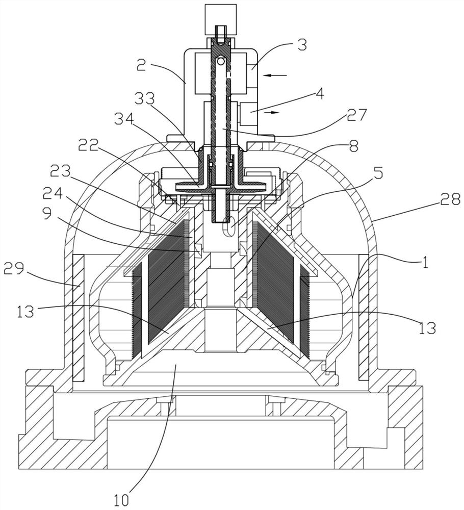
[0043] Such as figure 1 As shown, the present invention proposes a unidirectional heart disc centrifuge with spiral acceleration, including a drum 1, which is a common structure in the prior art, and forms an annular structure that can collect waste residue through the action of centrifugal force, so The top of the drum 1 is provided with a liquid inlet and outlet cover 2, which is used to pass in the mixed liquid and to discharge the light liquid. The liquid inlet and outlet cover includes a mixed liquid inlet pipe and a light liquid outlet pipe , a valve stem 27 is inserted into the top of the liquid inlet and outlet cover, the valve stem 27 is a hollow structure, and a slot is provided on the side wall, the mixed liquid inlet pipe communicates with the slot, and the valve ...


PUM


Abstract

The invention provides a disc stack centrifuge provided with a single centripetal pump with a spiral acceleration function and disc stack centrifugal equipment provided with the single centripetal pump. The disc stack centrifuge is characterized in that a liquid inlet and outlet cover body is used for introducing mixed liquid and discharging light liquid; a spiral guide mechanism is arranged at the lower part of the liquid inlet and outlet cover body; the spiral guide mechanism comprises a fixing cover, a hollow column is arranged in the center of the fixing cover, a mixed liquid inlet pipe is inserted into the hollow column, at least two sets of openings are formed in the side wall of the end of the hollow column, and threaded grooves are formed in the positions, corresponding to the openings, of the outer wall of the hollow column; and the bottom of the hollow column is communicated with a guide disc. In the internal flow channel structure of the disc stack centrifuge, after entering the liquid inlet channel, mixed liquid is immediately accelerated by a screw pump in the hollow column to be pushed into a bottom liquid inlet channel and is immediately accelerated to the same rotating speed of the centrifuge, the separation effect is accelerated, and the defect that liquid entering a rotary drum cannot be completely accelerated to the rotating speed of the centrifuge through a traditional centrifuge with a single centripetal pump is overcome.

Description

technical field [0001] The invention relates to the field of disc centrifugal equipment, in particular to a unidirectional disc centrifuge with spiral acceleration. Background technique [0002] Disc centrifuge is the core component of small purification equipment. It is usually installed above the vertical shaft in a vertical structure and rotates at a high speed driven by a motor. The disc centrifuge can separate dirty liquid (mixed liquid) into: net liquid (heavy liquid) ), oil (light liquid), solid impurities, that is, "liquid-liquid-solid" three-phase, widely used in machining, chemical, pharmaceutical, lubricating oil, hydraulic and other industries. The separation efficiency of a disc centrifuge depends on its internal structure design and speed, and low separation efficiency means poor separation accuracy of impurities per unit time, low cleanliness of net liquid, and small processing flow, which makes the purification equipment unable to meet the requirements of wor...

Claims


Application Information

Patent Timeline
Patent Type & Authority Applications(China)
IPC IPC(8): B04B1/08B04B7/14B04B7/00B04B11/04
CPCB04B1/08B04B7/00B04B7/14B04B11/04
Inventor 杜栋军李冰杜嘉澍
Owner 昆山金牛动力机械有限公司
Why Eureka
Try Eureka