
A positioning device and positioning method for a stacking crane clamp group

A positioning method and a technology for a fixture set, which are applied in the field of fixture sets for carbon block stacking cranes, can solve the problems of increasing a hoisting mechanism and a traveling mechanism, and achieve the effects of reducing motor power, reducing labor intensity, and chain action.

Active Publication Date: 2016-09-07
SHENYANG ALUMINIUM MAGNESIUM INSTITUTE
View PDF6 Cites 0 Cited by
  • Summary
  • Abstract
  • Description
  • Claims
  • Application Information

AI Technical Summary

Problems solved by technology

[0003] At present, the carbon block stacking crane operating under high load and high strength has the following problems: First, all operating actions are manually operated in the cab, which requires the driver to maintain a high degree of concentration at all times To avoid misoperation, misoperation is inevitable from the on-site use situation. Secondly, the jig set of the stacking crane is equipped with a guide device, because the position of the stacking crane is not easy for the driver to pick and place the carbon block. It is designed to avoid the shaking of the jig set of the stacking crane when a little adjustment is required for one alignment. Since the weight of the guide device is as much as 6 tons, accounting for more than 20% of the weight of the jig set, it is necessary to increase the motor of the lifting mechanism and the traveling mechanism power

Method used


Image

  • A positioning device and positioning method for a stacking crane clamp group
  • A positioning device and positioning method for a stacking crane clamp group
  • A positioning device and positioning method for a stacking crane clamp group

Examples


Embodiment Construction

[0028] The present invention will be described in detail below in conjunction with the accompanying drawings, but the protection scope of the present invention is not limited by the embodiments.

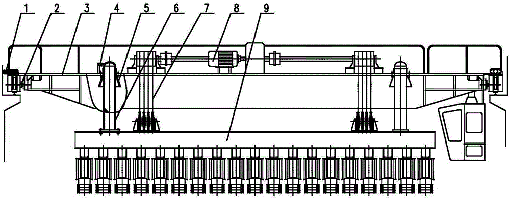
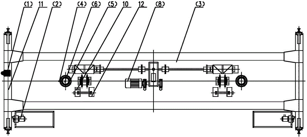
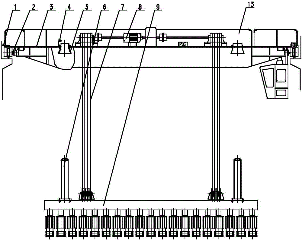
[0029] Such as Figure 1-Figure 3 As shown, the positioning device of the present invention's carbon block stacking crane clamp group mainly includes: No. 1 switch 1, No. 2 switch 4, positioning sleeve 5, positioning rod 6, No. 3 switch 10, etc., and its specific structure is as follows:

[0030] The positioning sleeve 5 is installed on the cover plate 3 of the stacking crane 13, the positioning rod 6 is installed on the top of the clamp group 9, and the positioning sleeve 5 matches the positioning rod 6. A lifting mechanism 8 is arranged on the cover plate 3, and the lifting mechanism 8 is connected with the clamp group 9 through a steel wire rope 7, and the positioning rod 6 is installed on the outside of the steel wire rope 7 of the clamp group 9.

[0031] In the present inventio...


PUM


Abstract

The invention relates to the field of fixture sets of carbon block stacking cranes, and in particular relates to a device and a method for positioning a fixture set of a carbon block stacking crane; the device is provided with a positioning sleeve and a positioning rod; the positioning sleeve is installed on a cover plate of the stacking crane; the positioning rod is installed at the upper part of the fixture set; the positioning sleeve is matched with the positioning rod; the positioning sleeve is of a combined structure; the lower part of the combined structure is shaped as a horn mouth; the upper part of the combined structure is shaped as a cylinder; a PLC (Programmable Logic Controller) is arranged on the cover plate of the stacking crane; and the output ends of a first switch, a second switch and a third switch are connected to the PLC controller, so that a detection signal is transmitted to the PLC controller. According to the invention, the carbon block stacking crane is precisely positioned; the motion is linked; programmed operation is realized; the labour intensity of workers is reduced; a guide device is omitted; and the motor power of a lifting mechanism and a travelling mechanism is reduced.

Description

technical field [0001] The invention relates to the field of clamp sets of a carbon block stacking crane, in particular to a positioning device and a positioning method for a clamp set of a carbon block stacking crane. Background technique [0002] With the rapid development of the aluminum industry, the demand for large-scale prebaked anodes is also increasing. In order to meet the needs of production development, the anode warehouses of large-scale electrolytic aluminum factories are also rapidly increasing the productivity of carbon block stacking cranes. At present, it has been clamped by 11 Each carbon block develops to hold 18-22 carbon blocks at a time. [0003] At present, the carbon block stacking crane operating under high load and high strength has the following problems: First, all operating actions are manually operated in the cab, which requires the driver to maintain a high degree of concentration at all times To avoid misoperation, misoperation is inevitable...

Claims


Application Information

Patent Timeline
Patent Type & Authority Patents(China)
IPC IPC(8): B66C13/08B66C13/48
CPCB66C13/08B66C13/48
Inventor 齐忠昱方明勋王林华
Owner SHENYANG ALUMINIUM MAGNESIUM INSTITUTE
Learn More