Supercharge Your Innovation With Domain-Expert AI Agents!

Environmental protection vacuum generator

A vacuum generating device, an environmentally friendly technology, applied in the direction of machines/engines, liquid variable displacement machinery, variable displacement pump components, etc., can solve the problems of complex and cumbersome production processes and processes, affecting the performance of parts and components, and achieve good filtration Function, extended service life, and high safety factor

Active Publication Date: 2017-04-12
JIANGSU SUYAN VALVE MASCH CO LTD
View PDF4 Cites 0 Cited by
  • Summary
  • Abstract
  • Description
  • Claims
  • Application Information

AI Technical Summary

Problems solved by technology

[0002] With the continuous improvement of science and technology, electronic devices in various electronic equipment are gradually developing towards the direction of miniaturization, high integration, high speed, high energy level and high power. With this rapid development, the upgrading of electronic products, new There are more and more products supporting the products, and the production process and technology of these products are very complicated and cumbersome
Large-scale enterprises generally use CNC machining and product finishing in industrial production, but in the process of processing, not only the compatibility of parts is required, but also better vacuum sealing is required. During the sealing process, dust cannot be exposed , and during the processing, the existing cutting fluid also needs to be removed in time, so as not to affect the performance of the parts, which requires a good environmental protection vacuum generator to complete this series of processing

Method used


Image

  • Environmental protection vacuum generator

Examples


Embodiment Construction

[0014] The present invention is described in further detail now in conjunction with accompanying drawing. These drawings are all simplified schematic diagrams, which only illustrate the basic structure of the present invention in a schematic manner, so they only show the configurations related to the present invention.

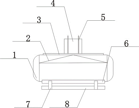
[0015] Such as figure 1 The preferred embodiment of the environment-friendly vacuum generating device of the present invention shown includes a vacuum pump 1, the upper surface of the vacuum pump 1 is provided with an air inlet pipe 3, the air inlet pipe 3 is connected with the vacuum pump 1, and the upper surface of the air inlet pipe 3 is provided with an electric control box 4 , the electric control box 4 passes through the intake pipe 3 and is fixed on the vacuum pump 1, the electric control box 4 is equipped with a heating strip 5, and the heating strip 5 extends in the vacuum pump 1 through the electric control box 4 and the intake pipe 3, and the vacuum...


PUM


Abstract

The invention discloses an environment-friendly vacuum generator. The environment-friendly vacuum generator comprises a vacuum pump, wherein an air inlet pipe is arranged on the upper surface of the vacuum pump, and the air inlet pipe and the vacuum pump are in communicated connection; an electric cabinet is arranged on the upper surface of the air inlet pipe, and the electric cabinet penetrates through the air inlet pipe to be fixed on the vacuum pump; heating strips are mounted on the electric cabinet, and the heating strips penetrate through the electric cabinet and the air inlet pipe respectively to extend into the vacuum pump; a filter is arranged in the vacuum pump and at a position close to the inner top surface of the vacuum pump; a cylinder is mounted on the lower surface of the vacuum pump, and the cylinder and the vacuum pump are connected through a fixing device; sliding rails are mounted on the cylinder, the tops of the sliding rails are connected with the cylinder, and a cylinder base is arranged at the bottoms of the sliding rails. The environment-friendly vacuum generator can effectively improve the vacuum quality, so that use in the next step can be realized better, a good filtering effect is realized, besides the heating is quick, the environment-friendly vacuum generator can be used quicker, in addition the environment-friendly vacuum generator is very convenient to operate and high in safety factors, and the service life of the environment-friendly vacuum generator can be prolonged better.

Description

technical field [0001] The invention relates to a vacuum generating device, in particular to an environment-friendly vacuum generating device. Background technique [0002] With the continuous improvement of science and technology, electronic devices in various electronic equipment are gradually developing towards the direction of miniaturization, high integration, high speed, high energy level and high power. With this rapid development, the upgrading of electronic products, new There are more and more products supporting the products, and the production process and technology of these products are very complicated and cumbersome. Large-scale enterprises generally use CNC machining and product finishing in industrial production, but in the process of processing, not only the compatibility of parts is required, but also better vacuum sealing is required. During the sealing process, dust cannot be exposed , and during the processing, the existing cutting fluid also needs to ...

Claims


Application Information

Patent Timeline
Patent Type & Authority Patents(China)
IPC IPC(8): F04B37/14F04B39/16F04B39/06F04B39/12
Inventor 韩正海韩文豪匡茜茜
Owner JIANGSU SUYAN VALVE MASCH CO LTD
Features
  • R&D
  • Intellectual Property
  • Life Sciences
  • Materials
  • Tech Scout
  • Unparalleled Data Quality
  • Higher Quality Content
  • 60% Fewer Hallucinations
Learn More