Supercharge Your Innovation With Domain-Expert AI Agents!

High-sealing-performance vacuumizing device

A vacuuming device and high-sealing technology, which is applied to liquid variable volume machinery, variable volume pump components, machines/engines, etc. Improve the quality of vacuuming, avoid air leakage, and facilitate the effect of switching

Active Publication Date: 2021-12-31
NANJING INST OF TECH
View PDF5 Cites 0 Cited by
  • Summary
  • Abstract
  • Description
  • Claims
  • Application Information

AI Technical Summary

Problems solved by technology

[0002]The air conditioner needs to be vacuumed before the refrigerant is injected. The existing vacuum device relies on turning the nut to connect the device with the connection port of the air conditioner external unit. During the process, the conical body fixed at the end of the device pushes the thimble at the air conditioner interface inward, connects the air conditioner external unit with the vacuuming device, and performs vacuuming operation; after the vacuuming is completed, loosen the nut to disassemble; However, during the disassembly process, since the disassembly of the screw nut is continuous, during the disassembly process, the cone gradually withdraws from the interface of the external unit of the air conditioner. Before it completely exits, the external air will enter the air conditioner through the loosened nut. In the external machine, air leakage will occur when the nut is loosened after vacuuming, and the absolute vacuuming task cannot be completed, which will affect the quality of work

Method used


Image

  • High-sealing-performance vacuumizing device
  • High-sealing-performance vacuumizing device
  • High-sealing-performance vacuumizing device

Examples


Embodiment Construction

[0026] The present invention will be more clearly and completely described below by way of a preferred embodiment with reference to the accompanying drawings, but the present invention is not limited to the scope of the described embodiment.

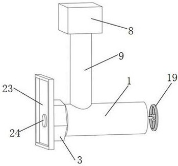
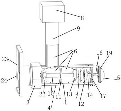
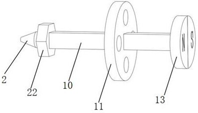
[0027] Such as figure 1 and figure 2 Shown is a high-tightness vacuuming device disclosed by the present invention, which includes a main vacuum pipeline 1, and one end of the main vacuum pipeline 1 is concentrically provided with a conical body 2 for conducting with the end to be vacuumed. The outer concentric sleeve with one end of the cone 2 is provided with a nut 3 for sealing connection with the end to be vacuumed, and a sliding guide mechanism is provided in the main vacuum pipeline 1 for the cone 2 to move along the axis of the main vacuum pipeline in a vacuum environment 4, and the driving mechanism 5 used to drive the movable part of the sliding guide mechanism 4 to move back and forth; between the sliding guiding mechanism 4 ...


PUM


Abstract

The invention discloses a high-sealing-performance vacuumizing device. The vacuumizing device comprises a main vacuum pipeline, one end of the main vacuum pipeline is concentrically provided with a cone-shaped body used for communicating with an end to be vacuumized, and the end, provided with the cone-shaped body, of the main vacuum pipeline is concentrically sleeved with a nut. A sliding guide mechanism used for enabling the cone-shaped body to move in the axis direction of the main vacuum pipeline in a vacuum environment and a driving mechanism used for driving a movable part of the sliding guide mechanism to move back and forth are arranged in the main vacuum pipeline. A partition plate used for blocking the main vacuum pipeline so as to form a vacuum cavity during vacuumizing is arranged between the sliding guide mechanism and the driving mechanism. The driving mechanism drives the sliding guide mechanism to move in the vacuum cavity through repulsion and attraction between magnets, and a communicating pipeline communicating with an external vacuum pump is arranged on the vacuum cavity. According to the high-sealing-performance vacuumizing device, the principle of attraction and repulsion of magnetic poles is utilized, operation and control of the cone-shaped body in a closed space are achieved, air leakage is avoided during disassembly after vacuumizing is completed, the sealing performance is good, and the vacuumizing quality is improved.

Description

technical field [0001] The invention relates to the technical field of vacuuming equipment, in particular to a high-tightness vacuuming device. Background technique [0002] The air conditioner needs to be vacuumed before injecting refrigerant. The existing vacuum device relies on turning the nut to connect the device with the connection port of the external unit of the air conditioner. The thimble of the air conditioner is jacked up inward, and the external unit of the air conditioner is connected with the vacuuming device for vacuuming operation; after the vacuuming is completed, the nut is loosened and disassembled; however, during the disassembly process, the disassembly is performed continuously due to the rotation of the nut Yes, during the disassembly process, the cone gradually withdraws from the interface of the air conditioner external unit. Before it completely exits, the external air will enter the air conditioner external unit through the loosened nut, so the mo...

Claims


Application Information

Patent Timeline
Patent Type & Authority Applications(China)
IPC IPC(8): F04B39/14F25B45/00
CPCF04B39/14F25B45/00
Inventor 曾宪阳杨红莉张国玉邱航俞光
Owner NANJING INST OF TECH
Features
  • R&D
  • Intellectual Property
  • Life Sciences
  • Materials
  • Tech Scout
  • Unparalleled Data Quality
  • Higher Quality Content
  • 60% Fewer Hallucinations
Learn More