Supercharge Your Innovation With Domain-Expert AI Agents!

Filtered Cathodic Arc Deposition Method and Apparatus

a cathodic arc and filtering technology, applied in vacuum evaporation coatings, electrolysis components, coatings, etc., can solve the problems of contaminating the coating, affecting the application range, and causing macroparticles to form, and achieve the effect of deflection of plasma flow

Inactive Publication Date: 2010-07-08
G&H TECH LLC
View PDF27 Cites 0 Cited by
  • Summary
  • Abstract
  • Description
  • Claims
  • Application Information

AI Technical Summary

Benefits of technology

This solution significantly reduces metal ion losses and improves coating quality by effectively deflecting macroparticles and controlling plasma composition, allowing for the application of coatings on larger substrates with improved uniformity and purity.

Problems solved by technology

An undesirable result of the vacuum arc coating technique is the creation of macroparticles, which are formed from molten cathode material vaporized by the arc.
These macroparticles are ejected from the surface of the cathode material, and can contaminate the coating as it is deposited on the substrate.
The resulting coating may be pitted or irregular, which at best presents an aesthetic disadvantage, but is particularly problematic in the case of coatings on precision instruments.
The configuration of this apparatus limits the dimensions of the substrate to be coated to 200 mm, which significantly limits the range of its application.
Furthermore, there is no provision in the tore-shaped plasma duct for changing the configuration of the magnetic field, other than the magnetic field intensity.
This is related to the turbulence of the plasma stream in the tore, which causes a drastic rise in the diffusion losses of ions on the tore walls.
This results in an undesirable period where the magnetic field is zero; the arc is therefore not continuous, and is not controlled during this period.
This ‘pseudo-random’ steering method cannot consistently produce reliable or reproducible coatings.
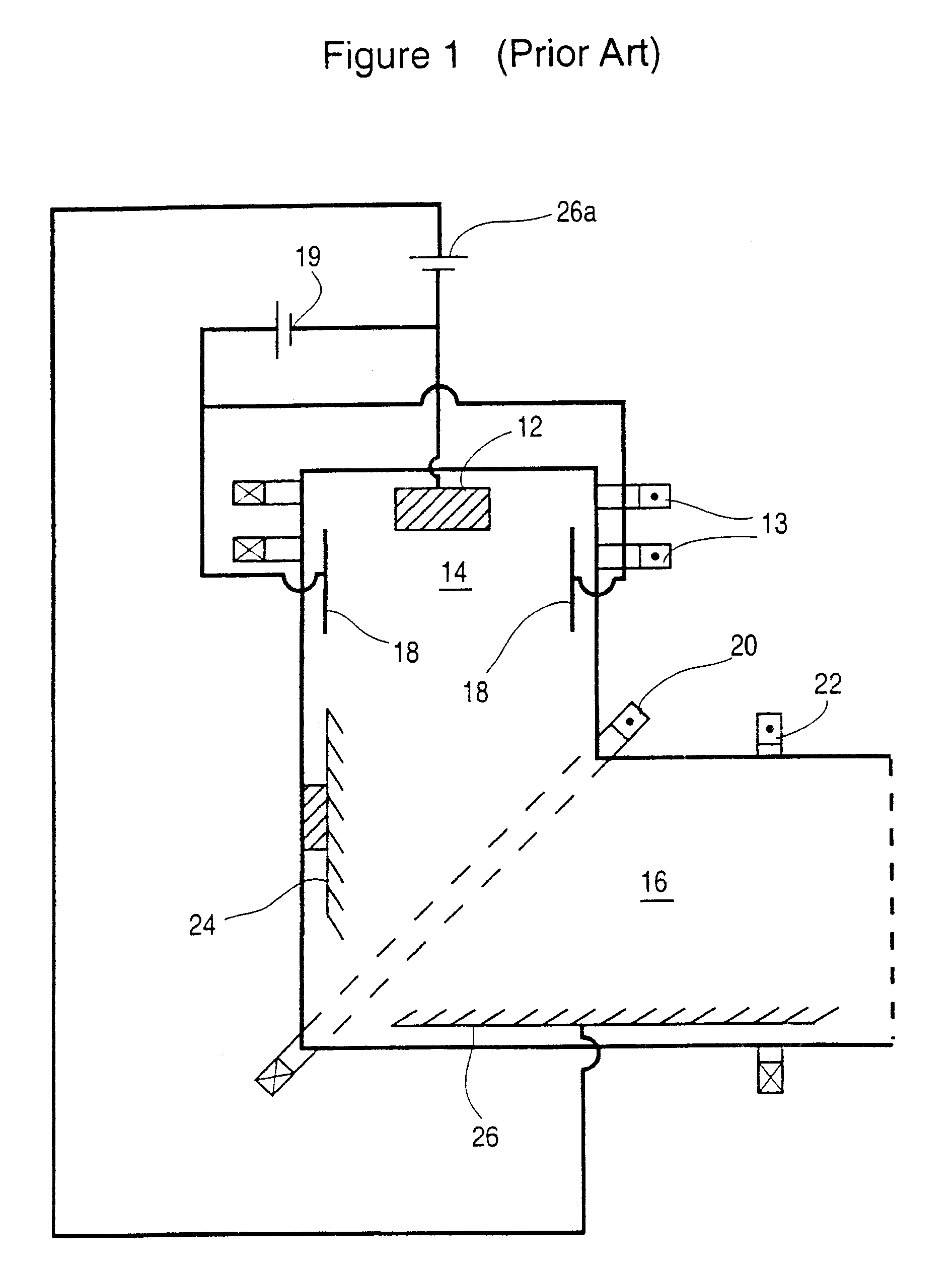
In the prior art, most of the surface of the deflecting electrode is disposed in a position where the transversal component of the magnetic field is strong and the tangential component of the magnetic field is relatively weak, which results in low magnetic insulation along the deflecting electrode.
This is a disadvantage of the systems taught by Gorokhovsky and Welty, as it results in a weak deflecting electric field which is not strong enough to change the trajectory of heavy metal ions, such as Gf+ and W+, toward the substrate to be coated.
Even in the case lighter ions such as Al+ and Ti+ the degree of ion deflection is slight, which results in substantial losses of metal ions before the plasma reaches the position of the substrate(s).
Such filters create large plasma losses and a very low plasma yield, because the baffles destroy the geometry of the plasma duct.
However, this solution affects macroparticles only and does not allow for control of the plasma composition in the coating chamber, for example where it would be desirable to expose the substrate(s) to an ionized plasma without a metal component, as in plasma immersed processes such as ion implantation, ion cleaning, ion nitriding and the like.

Method used


Image

  • Filtered Cathodic Arc Deposition Method and Apparatus
  • Filtered Cathodic Arc Deposition Method and Apparatus
  • Filtered Cathodic Arc Deposition Method and Apparatus

Examples


example 1

Filtered Arc Plasma Immersed Ion Cleaning

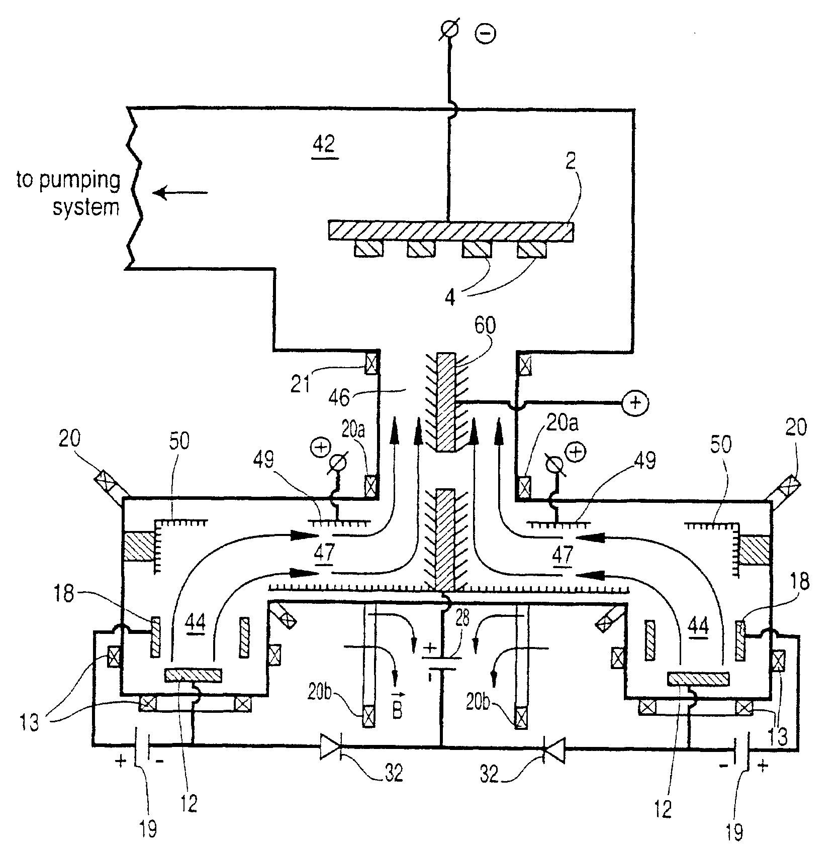
[0130]The arc coating apparatus shown in FIG. 3b was used in this process. The apparatus was equipped with two dual-filtered arc sources, having round cathodes 12 measuring 3″ in diameter and 2″ in height, one filtered arc source having titanium targets and the other having chromium targets. The exit opening of the filtered arc sources was equipped with load lock shutters 80a, 80b, electron-permeable to provide a free passage of electron current from the cathode targets 12 to distal auxiliary anodes 70 to thereby establish an auxiliary arc discharge. Augmented by the auxiliary arc discharge the ionization and activation of the gaseous component of the plasma environment in the coating chamber 42 was significantly increased (up to 30 to 40% in comparison with approximately 1 to 3% gas ionization rate without the auxiliary arc discharge).

[0131]2″ diameter, ¼″ thick HSS disc coupons as substrates 4 were washed in a detergent containing a water s...

example 2

Ion Nitriding and Ion Implantation in the Auxiliary Arc Discharge

[0132]The apparatus and substrate coupons 4 of Example 1 were used in this process. After the ion cleaning stage the gas mixture was changed to nitrogen as an ion nitriding gas, injected to create a total pressure ranging from 2×10⁻⁴ to 8×10⁻⁴ Torr. For ion nitriding the substrates 4 were preliminary heated to 300° C. to 450° C. using conventional heaters (not shown) installed in front of the distal auxiliary anodes 70 in the coating chamber 42. A self-bias voltage was established at a range from 100 to 400 volts. The current applied to distal auxiliary anodes 70 was set at 100 amps and the ion nitriding stage was performed for 1 hour.

[0133]For low-energy ion implantation the substrate temperature was set to a lower level, about 150 to 300° C., and the bias voltage ranged from 200 to 3000 volts. The ion implantation stage was performed for 1 hour.

[0134]The ion nitriding and ion implanted layers were characterized by st...

example 3

Auxiliary Arc Plasma Immersed Deposition of Chromium Nitride Filtered Arc PVD Coating

[0135]The apparatus of FIG. 3b was equipped with the same cathode targets 12 as in Example 1. The same substrate coupons 4 as in Example 1 were installed on the rotary satellites of substrate holder 2 with single rotation and preheated to 400° C. by conventional heaters installed in the coating chamber 42. After ion cleaning as described in Example 1 the lock load shutter 80b of the filtered arc source with the chromium cathode targets 12 was opened and the gas was changed to pure nitrogen with total pressure of 2×10⁻⁴ to 3×10⁻⁴ Torr. The deflecting and focusing magnetic coils 13, 20 of the filtered arc source magnetic systems were activated to deflect the chromium plasma stream toward substrates. The total current of the deflecting anode 50 was established at 50 amps, and the total current of the repelling anode was established at 40 amps. The current between chromium cathodes 12 and distal auxilia...


PUM

PropertyMeasurementUnit
diameteraaaaaaaaaa
sizeaaaaaaaaaa
ionization rateaaaaaaaaaa

Abstract

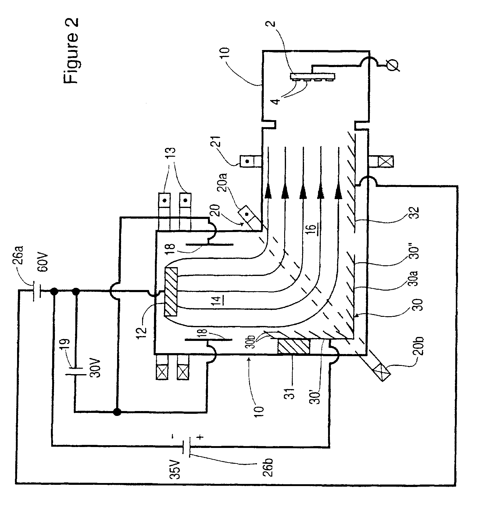
An apparatus for the application of coatings in a vacuum comprising a plasma duct surrounded by a magnetic deflecting system communicating with a first plasma source and a coating chamber in which a substrate holder is arranged off of an optical axis of the plasma source, has at least one deflecting electrode mounted on one or more walls of the plasma duct. In one embodiment an isolated repelling or repelling electrode is positioned in the plasma duct downstream of the deflecting electrode where the tangential component of a deflecting magnetic field is strongest, connected to the positive pole of a current source which allows the isolated electrode current to be varied independently and increased above the level of the anode current. The deflecting electrode may serve as a getter pump to improve pumping efficiency and divert metal ions from the plasma flow. In a further embodiment a second arc source is activated to coat the substrates while a first arc source is activated, and the magnetic deflecting system for the first arc source is deactivated to confine plasma to the cathode chamber but permit electrons to flow into the coating chamber for plasma immersed treatment of the substrates. A load lock shutter may be provided between the plasma duct and the coating chamber further confine the plasma from the first arc source.

Description

CROSS-REFERENCE TO RELATED APPLICATIONS[0001]The present application claims the benefits under all relevant U.S. statutes, including 35 U.S.C. 120, to currently pending application Ser. No. 11 / 890,736, filed Aug. 6, 2007, titled FILTERED CATHODIC ARC DEPOSITION METHOD AND APPARATUS, which is a continuation of application Ser. No. 10 / 713,529, filed Nov. 13, 2003, now U.S. Pat. No. 7,252,745 B1, which is a continuation of application Ser. No. 09 / 826,940, filed Apr. 6, 2001, now U.S. Pat. No. 6,663,755, which in turn claims priority under 35 U.S.C. 119 to Canadian Application No. 2,305,938, filed Apr. 10, 2000.STATEMENT REGARDING FEDERALLY SPONSORED RESEARCH OR DEVELOPMENT[0002]Not applicableREFERENCE TO SEQUENCE LISTING, A TABLE, OR A COMPUTER PROGRAM COMPACT DISC APPENDIX[0003]Not ApplicableFIELD OF THE INVENTION[0004]This invention relates to the application of coatings in a vacuum apparatus. In particular, this invention relates to an apparatus which generates a plasma of electrica...

Claims


Application Information

Patent Timeline
Patent Type & Authority Applications(United States)
IPC IPC(8): C23C14/28C23C14/02C23C14/06C23C14/16C23C14/32C23C14/35C23C14/48C23C16/36H01J37/32
CPCC23C14/022C23C14/0605C23C14/0641C23C14/0647C23C14/16C23C14/325C23C14/355C23C14/48C23C16/36H01J37/32055H01J37/3266
Inventor GOROKHOVSKY, VLADIMIR
Owner G&H TECH LLC
Features
  • R&D
  • Intellectual Property
  • Life Sciences
  • Materials
  • Tech Scout
  • Unparalleled Data Quality
  • Higher Quality Content
  • 60% Fewer Hallucinations
Learn More