High-pressure steam system for two-pull-one unit of fuel gas thermal power plant and start-stop control method of high-pressure steam system

A high-pressure steam, start-stop control technology, applied in the direction of the control system, steam generation, steam generation device, etc., can solve the problems of unable to isolate the exhaust steam of the high-pressure cylinder, unable to balance the pressure difference between the front and rear of the steam electric door, etc., to achieve automatic The effect of parallel steam

Active Publication Date: 2015-06-10
NORTH CHINA ELECTRICAL POWER RES INST +1
View PDF4 Cites 2 Cited by
  • Summary
  • Abstract
  • Description
  • Claims
  • Application Information

AI Technical Summary

Problems solved by technology

[0002] The main function of the high-pressure steam system in a gas-fired thermal power plant is to connect the high-pressure steam drum of the waste heat boiler to the high-pressure cylinder of the steam turbine to do work. To balance the pressure difference between the front and back of the parallel steam electric door, it is impossible to isolate the high-pressure cylinder exhaust steam to the medium-pressure steam drum reheater
In addition, the existing high-pressure steam system of the gas-fired thermal power plant cannot realize the automatic input of the high-pressure steam system on the local side when the high-pressure steam system on the local side is withdrawn; When the high-pressure steam system on the other side is put into operation, the automatic paralleling of the high-pressure steam system on this side can be realized.

Method used


Image

  • High-pressure steam system for two-pull-one unit of fuel gas thermal power plant and start-stop control method of high-pressure steam system
  • High-pressure steam system for two-pull-one unit of fuel gas thermal power plant and start-stop control method of high-pressure steam system
  • High-pressure steam system for two-pull-one unit of fuel gas thermal power plant and start-stop control method of high-pressure steam system

Examples


Embodiment Construction

[0048]The following will clearly and completely describe the technical solutions in the embodiments of the present invention with reference to the accompanying drawings in the embodiments of the present invention. Obviously, the described embodiments are only some, not all, embodiments of the present invention. Based on the embodiments of the present invention, all other embodiments obtained by persons of ordinary skill in the art without making creative efforts belong to the protection scope of the present invention.

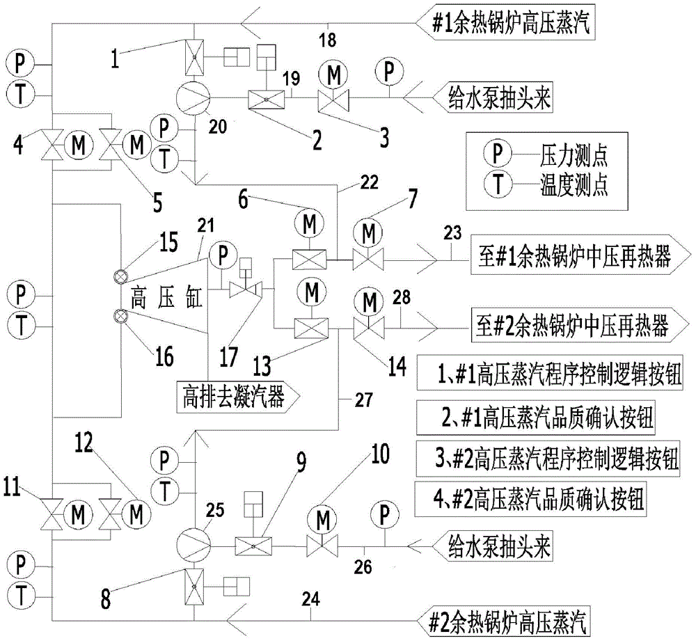
[0049] The embodiment of the present invention provides a high-pressure steam system of a two-to-one unit in a gas-fired thermal power plant, such as figure 1 As shown, the high-pressure steam system of the two-to-one unit of the gas-fired thermal power plant includes: #1 high-pressure steam system, #2 high-pressure steam system and steam turbine high-pressure cylinder 21, #1 high-pressure steam system is connected to the steam turbine high-pressure cylinder 21 ...


PUM


Abstract

The invention relates to a high-pressure steam system for a two-pull-one unit of a fuel gas thermal power plant and a start-stop control method of the high-pressure steam system. The high-pressure steam system comprises a first high-pressure steam system, a second high-pressure steam system and a steam turbine high-pressure cylinder, wherein the first high-pressure steam system comprises a first high-pressure steam pipeline, a first high-pressure steam converging electric door, a first high-pressure steam converging bypass electric door, a first high-pressure bypass control valve, a first high side temperature-reducing water pipeline, a first high side temperature-reducing water regulating valve and a first high side temperature-reducing water electric valve; the second high-pressure steam system comprises a second high-pressure steam pipeline, a second high-pressure steam converging electric door, a second high-pressure steam converging bypass electric door, a second high-pressure bypass control valve, a second high side temperature-reducing water pipeline, a second high side temperature-reducing water regulating valve and a second high side temperature-reducing water electric valve. According to the invention, automatic investment can be realized in the steam withdrawing state of the medium-pressure steam system on the side; in the investment state, automatic steam withdrawing or automatic steam converging of the medium-pressure steam system on the side is realized.

Description

technical field [0001] The invention relates to the high-pressure steam technology of a gas-fired thermal power plant, in particular to a high-pressure steam system of a two-to-one unit in a gas-fired thermal power plant and a start-stop control method thereof. Background technique [0002] The main function of the high-pressure steam system in a gas-fired thermal power plant is to connect the high-pressure steam drum of the waste heat boiler to the high-pressure cylinder of the steam turbine to do work. If the pressure difference between the front and rear of the electric parallel valve is balanced, it is impossible to isolate the exhaust steam from the high-pressure cylinder to the medium-pressure drum reheater. In addition, the existing high-pressure steam system of the gas-fired thermal power plant cannot realize the automatic input of the high-pressure steam system on the local side when the high-pressure steam system on the local side is withdrawn; When the high-press...

Claims


Application Information

Patent Timeline
Patent Type & Authority Applications(China)
IPC IPC(8): F22B33/18F22B35/00F01D17/10
Inventor 任彦黄葆华司派友刘双白吕炜左川
Owner NORTH CHINA ELECTRICAL POWER RES INST
Why Eureka
Try Eureka