
Heat exchanger vacuum hot water boiler

A hot water boiler and heat exchanger technology, applied in the field of hot water boilers, can solve the problems of poor pressure bearing capacity of the boiler shell, poor boiler steam quality, complicated manufacturing process, etc., and achieve low manufacturing cost, simplified manufacturing process, and high heat transfer efficiency. good effect

Inactive Publication Date: 2015-06-10
广州贝龙环保热力设备股份有限公司
View PDF9 Cites 1 Cited by
  • Summary
  • Abstract
  • Description
  • Claims
  • Application Information

AI Technical Summary

Problems solved by technology

[0002] In traditional vacuum boilers, the heat exchanger, smoke pipe and furnace are all placed inside the pot shell, and the pot shell is made into a built-in structure with an oblong cross section. There is also a steam chamber separated from the pot shell, and the heat exchanger is fixed. In the steam chamber, the pot shell is made into a cylindrical external structure that is welded and fixed to the shell of the steam chamber. Regardless of the structure, the heat exchanger adopts a traditional cuboid structure. The heat exchanger with this structure, its The production process is complicated, the production cost is high, the maintenance is inconvenient, and the steam space is too large. The boiler with this structure has the disadvantages of poor steam quality, high noise, and poor pressure bearing capacity of the boiler shell.

Method used


Image

  • Heat exchanger vacuum hot water boiler
  • Heat exchanger vacuum hot water boiler

Examples


Embodiment Construction

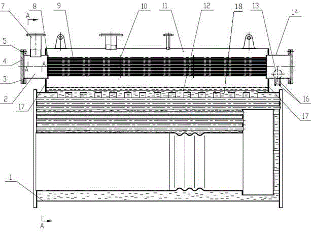
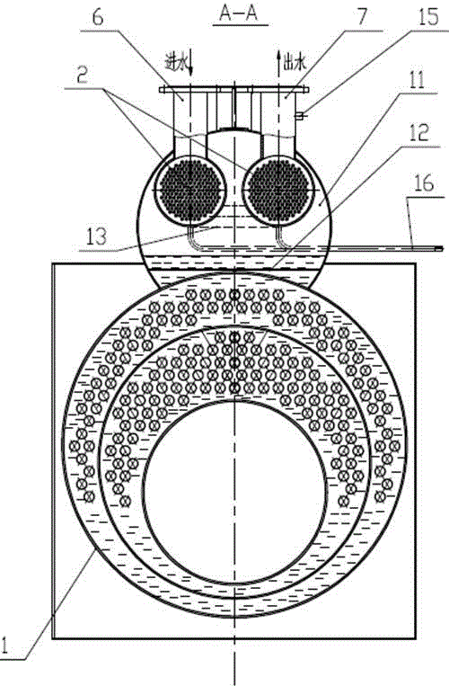
[0016] Such as figure 1 , 2 As shown, the heat exchanger vacuum hot water boiler of the present invention includes a boiler body 1, a cylindrical steam chamber 11 located above the boiler body 1, an inlet pipe seat 6 and an outlet pipe seat 7, and more than two heat exchange The two ends of the steam chamber 11 are respectively provided with sealing plates 17; a plurality of square holes 18 are opened between the boiler body 1 and the steam chamber 11, and the lower part of the steam chamber 11 is welded with a steel wire mesh 12;

[0017] The heat exchanger 2 includes a cylindrical front tube box 3 fixed on one end sealing plate 17, a cylindrical rear tube box 14 fixed on the other end sealing plate 17, and a tube located in the steam chamber 11 communicating with the front tube box 3. The heat exchange tubes 9 of the tube box 3 and the rear tube box 14, the front tube box 3 and the rear tube box 14 are respectively welded with a tube plate 8, the heat exchange tube 9 is fix...


PUM


Abstract

The invention provides a heat exchanger vacuum hot water boiler with a good heat transfer effect and low manufacturing cost. The heat exchanger vacuum hot water boiler comprises a boiler body, a cylindrical steam chamber, a water inlet pipe seat, a water outlet pipe seat, two or more heat exchangers, wherein the cylindrical steam chamber is positioned above the boiler body; sealing plates are respectively arranged at both ends of the steam chamber; a plurality of square holes are formed in a part between the boiler body and the steam chamber and used for communicating the boiler body with the steam chamber; a steel wire mesh is welded at the lower part of the steam chamber. According to the heat exchanger vacuum hot water boiler provided by the invention, a front pipe box and a rear pipe box of the heat exchangers are made into a cylinder shape and are made of round pipes with the standard specification, so that flanges and flange covers, which are connected with the front and rear pipe boxes, can have the corresponding standard specification, and thus, the manufacturing process is simplified, manufacturing cost is reduced, and the manufacturing period is shortened and deformation generated in the welding process is much smaller than that of a cuboid-shaped structure; the heat exchangers are more convenient to overhaul; arrangement of heat exchange pipes is more dispersed than that of single heat exchangers, so that the heat transfer effect is further enhanced.

Description

technical field [0001] The invention relates to a hot water boiler, in particular to a heat exchanger vacuum hot water boiler. Background technique [0002] In traditional vacuum boilers, the heat exchanger, smoke pipe and furnace are all placed inside the pot shell, and the pot shell is made into a built-in structure with an oblong cross section. There is also a steam chamber separated from the pot shell, and the heat exchanger is fixed. In the steam chamber, the pot shell is made into a cylindrical external structure that is welded and fixed to the shell of the steam chamber. Regardless of the structure, the heat exchanger adopts a traditional cuboid structure. The heat exchanger with this structure, its The production process is complicated, the production cost is high, and the maintenance is inconvenient, which also leads to an excessively large steam space. The boiler with this structure also has disadvantages such as poor steam quality, high noise, and poor pressure be...

Claims


Application Information

Patent Timeline
IPC IPC(8): F24H1/22F24H9/00
Inventor 梁福任姜哲梁芦茂国
Owner 广州贝龙环保热力设备股份有限公司
Learn More