
Low-impedance broadband test fixture

A broadband testing, low-impedance technology, applied in the field of radio frequency microwave measurement, can solve the problems of burnt devices, easy to burn devices, narrow working bandwidth, etc., and achieve the effect of reducing low-frequency oscillation, reducing the risk of burning tubes, and reducing the degree of impedance mismatch

Inactive Publication Date: 2015-06-10
SHANGHAI LIANXING ELECTRONICS
View PDF4 Cites 4 Cited by
  • Summary
  • Abstract
  • Description
  • Claims
  • Application Information

AI Technical Summary

Problems solved by technology

When a 50Ω test fixture is used to test a large gate width and high power LDMOS device with a small impedance, due to the serious impedance mismatch, low frequency oscillation is caused, and the device is easily burned
The fixture used for package-level testing has a certain impedance transformation, which can be transformed from 50 ohms to more than ten ohms. After the transformation, the impedance is still relatively high, and it is easy to oscillate at low frequency and burn the device
In addition, with bias circuit power supply, the fixture is affected by the filter capacitance of the bias circuit, and the working bandwidth is very narrow

Method used


Image

  • Low-impedance broadband test fixture

Examples


Embodiment Construction

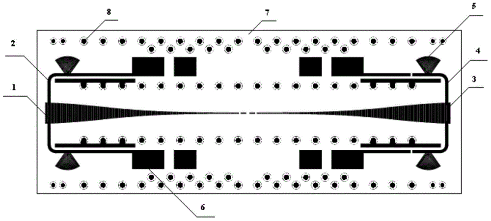
[0015] see figure 1 , a low-impedance broadband test fixture provided by an embodiment of the present invention includes: an impedance transformer and a support; the impedance transformer is fixed on the support for realizing impedance transformation of the fixture to match various types of LDMOS to be tested The device reduces the degree of impedance mismatch; the impedance converter includes: a first tapered microstrip line 1, a first bias circuit 2, a second tapered microstrip line 3 and a second bias circuit 4; the first tapered microstrip line 1. The first bias circuit 2, the second gradient microstrip line 3 and the second bias circuit 4 are printed on the PCB board 7 as high-frequency circuits; the first gradient microstrip line 1 and the second gradient microstrip line 3 The LDMOS device to be tested is clamped; the first bias circuit 2 is connected to the first tapered microstrip line 1 ; the second bias circuit 4 is connected to the second tapered microstrip line 3 ....


PUM

PropertyMeasurementUnit
Lengthaaaaaaaaaa

Abstract

An improved low-impedance test fixture comprises: an impedance converter and a support piece. The impedance converter is fixed on the support piece. The impedance converter comprises: a first tapered microstrip line, a first bias circuit, a second tapered microstrip line, and a second bias circuit. The first tapered microstrip line, the first bias circuit, the second tapered microstrip line, and the second bias circuit are printed on a PCB board. The first tapered microstrip line and the second tapered microstrip line hold an LDMOS device under test. The first bias circuit and the first tapered microstrip line are connected. The second bias circuit and the second tapered microstrip line are connected. By using a tapered microstrip line, the improved low-impedance test fixture increase an impedance conversion range of the test fixture, reduces a degree of impedance mismatch between the fixture and an LDMOS device under test, reduces low-frequency oscillations, and reduces a risk of transistor burnout.

Description

technical field [0001] The invention relates to the technical field of radio frequency microwave measurement, in particular to a low-impedance broadband test fixture. Background technique [0002] When using the Loadpull system to test the power amplifier tube, the impedance of the test fixture needle is 50Ω, and the impedance transformation function is not designed. When a 50Ω test fixture is used to test a large gate width and high-power LDMOS device with a small impedance, due to a serious impedance mismatch, low-frequency oscillations are caused, and the device is easily burned. The fixture used for package-level testing has a certain impedance transformation, which can be transformed from 50 ohms to more than ten ohms. The transformed impedance is still relatively high, and it is easy to oscillate at low frequency and burn out the device. In addition, when the bias circuit is used for power supply, the fixture is affected by the filter capacitance of the bias circuit, ...

Claims


Application Information

Patent Timeline
IPC IPC(8): G01R1/04
CPCG01R1/0466G01R31/2621
Inventor 丛密芳王帅李科任建伟杜寰
Owner SHANGHAI LIANXING ELECTRONICS
Learn More