
Wire wrapping method and system for reducing difference circuit impedance mismatch degree

A technology of impedance mismatch and differential circuit, which is applied in the direction of printed circuit, printed circuit manufacturing, printed circuit components, etc.

Inactive Publication Date: 2014-09-10
INSPUR BEIJING ELECTRONICS INFORMATION IND
View PDF3 Cites 12 Cited by
  • Summary
  • Abstract
  • Description
  • Claims
  • Application Information

AI Technical Summary

Problems solved by technology

[0004] The present invention provides a winding method and system for reducing the degree of impedance mismatch of differential circuits, so as to solve the problem of how to realize the technology of reducing the adverse effects caused by the impedance mismatch of differential circuits on the basis of ensuring the equal length of differential pair signals question

Method used


Image

  • Wire wrapping method and system for reducing difference circuit impedance mismatch degree
  • Wire wrapping method and system for reducing difference circuit impedance mismatch degree
  • Wire wrapping method and system for reducing difference circuit impedance mismatch degree

Examples


Embodiment Construction

[0031] In order to make the purpose, technical solution and advantages of the present invention more clear, the embodiments of the present invention will be described in detail below in conjunction with the accompanying drawings. It should be noted that, in the case of no conflict, the embodiments in the present application and the features in the embodiments can be combined arbitrarily with each other.

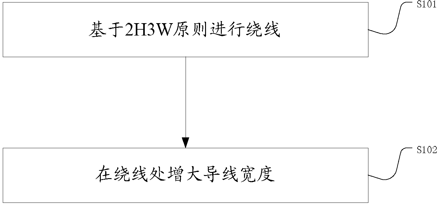
[0032] figure 1 It is a flow chart of the winding method for reducing the degree of impedance mismatch of the differential circuit in this embodiment.

[0033] S101 Winding based on the setting principles, the setting principles include: 2H3W principle;

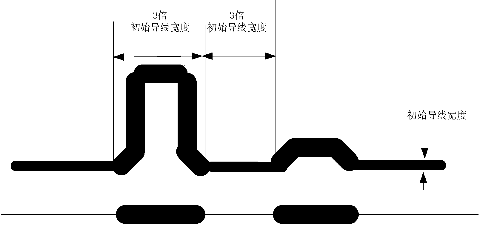
[0034] The setting principle also includes: the width of each winding is three times the width of the initial wire, so as to ensure that the sudden change in impedance at the winding will not be too large; the initial wire width is the width of the wire that has not been wound;

[0035] S102 increasing the width of the wir...


PUM


Abstract

The invention provides a wire wrapping method and system for reducing difference circuit impedance mismatch degree. The method includes that wire wrapping is performed on the basis of a set principle, the set principle includes a 2H3W principle, and the width of a guide wire is increased at the position of the wire wrapping. According to the wire wrapping method and system for reducing the difference circuit impedance mismatch degree, bag influences which are brought by difference circuit impedance mismatch are reduced on the basis of guaranteeing equal-length differential pair signals.

Description

technical field [0001] The invention relates to the field of differential circuit impedance adjustment, in particular to a winding method and system for reducing the degree of impedance mismatch of a differential circuit. Background technique [0002] At present, the transmission rate of signals is getting higher and higher, and the consistency requirements of impedance matching are more stringent. Impedance matching means that the load impedance is equal to the characteristic impedance of the transmission line. [0003] In the differential signal system, the unequal length of the differential pair signals and the mismatch of impedance will reduce the difference between the differential pair signals, increase the bit error rate, generate common mode noise, and increase electromagnetic interference radiation (EMI). At present, when designing the PCB board of the differential signal system, due to the influence of the wiring environment, the differential pair signals often hav...

Claims


Application Information

Patent Timeline
IPC IPC(8): H05K1/02H05K3/00
Inventor 胡立燕张柯柯
Owner INSPUR BEIJING ELECTRONICS INFORMATION IND
Learn More