Light pressure demonstration instrument

A demonstrator and laser technology, applied in the field of optical pressure demonstrator, can solve the problems of complex equipment, difficult to obtain, unable to realize rotation, etc., and achieve the effect of simple equipment and convenient operation.

Pending Publication Date: 2015-06-10
CHINA SCI & TECH MUSEUM
View PDF6 Cites 0 Cited by
  • Summary
  • Abstract
  • Description
  • Claims
  • Application Information

AI Technical Summary

Problems solved by technology

However, the equipment used by Lebedev has the following defects: the equipment is complicated, it is focused by a set of lens groups, and the demonstration is difficult. For many years, the popular science circles and universities have failed to demonstrate it intuitively.

Method used


Image

  • Light pressure demonstration instrument
  • Light pressure demonstration instrument
  • Light pressure demonstration instrument

Examples


Embodiment Construction

[0036] A light pressure demonstrator provided by the present invention will be described in detail below with reference to the accompanying drawings and specific embodiments. At the same time, it is explained here that in order to make the embodiments more detailed, the following embodiments are the best and preferred embodiments, and those skilled in the art can also adopt other alternative ways to implement for some known technologies; and the accompanying drawings It is only for more specific description of the embodiments, but not intended to specifically limit the present invention.

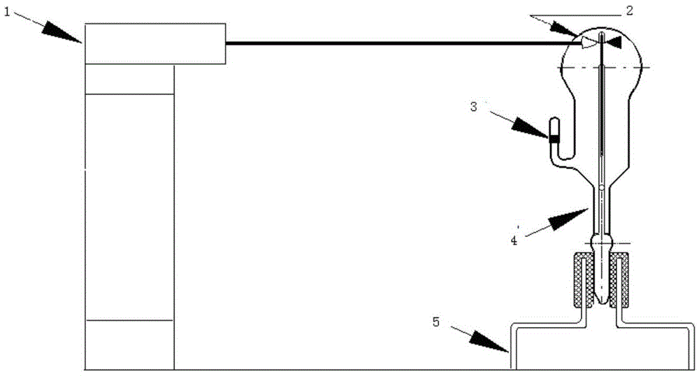
[0037] In the background, the challenges faced in implementing photopressure demonstrations have already been mentioned. The present invention designs a kind of light pressure demonstrator just in order to solve above-mentioned difficulty. figure 1 A structural principle diagram of the light pressure demonstrator of the embodiment of the present invention is shown. Such as figure 1 As sho...


PUM


Abstract

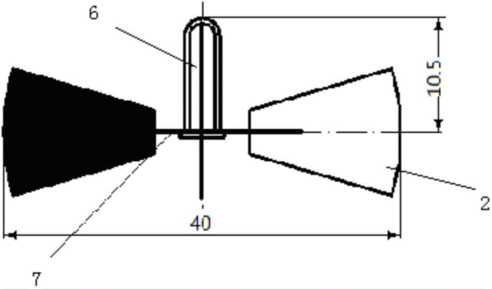
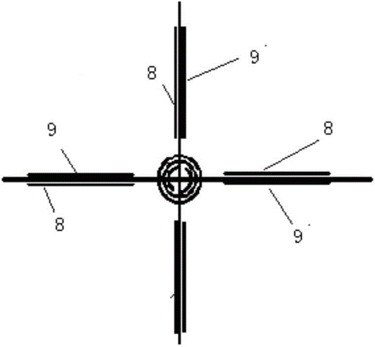
The invention provides a novel light pressure demonstration instrument. The light pressure demonstration instrument comprises a laser, at least two rotation blades, at least two bearings and a glass vacuum chamber. Each rotation blade comprises a silver plated face and a blacked face, and the at least two rotation blades are arranged on the bearings coaxially. The silver plated faces and the blacked faces of the adjacent blades are arranged alternately in the clockwise or anti-clockwise direction, and the blades and the laser are arranged in the same horizontal plane. The rotation blades and the bearings are accommodated in the glass vacuum chamber, and the bearings are arranged on supports. The demonstration instrument is simple in apparatus and convenient to operate, an impeller rotates continuously from the white faces to the black faces under the action of light pressure instead of the swinging of suspension elements, and accordingly, the light pressure action and 'power' can be seen clearly and visually.

Description

technical field [0001] The invention relates to an optical demonstration device, in particular to an optical pressure demonstration instrument used in optics. Background technique [0002] In order to prove the existence of light pressure, many physicists have rushed to this scientific research. If the light pressure can be successfully demonstrated, it will broaden the infinitely bright prospects for its application: human beings are studying the tool of space navigation - the solar sail, and its power comes from the light pressure. In 1901, Russian physicist Peter Nikolaevich Lebedev designed an experiment, discovered light pressure for the first time, and published "Experimental Research on Light Pressure", which proved that light pressure the granularity. Following this, American physicists E.F. Nichols and G.F. Hull also measured the pressure of light with precise experiments. Lebedev uses arc light as a light source, and through the focusing of the lens group, the l...

Claims


Application Information

Patent Timeline
IPC IPC(8): G09B23/22
CPCG09B23/22
Inventor 潘玮胡滨洪唯佳
Owner CHINA SCI & TECH MUSEUM
Why Eureka
Try Eureka