Transformer coil, winding method of transformer coil and transformer

A technology of transformer coil and winding method, which is applied in the direction of transformer/inductor coil/winding/connection, inductor/transformer/magnet manufacturing, coil manufacturing, etc. The problem of the same number, etc., to achieve the effect of improving the coupling coefficient and the number of turns are the same

Active Publication Date: 2017-05-24
ZTEV
View PDF5 Cites 0 Cited by
  • Summary
  • Abstract
  • Description
  • Claims
  • Application Information

AI Technical Summary

Problems solved by technology

However, when the required number of winding turns is an odd number of turns, assuming that the required number of winding turns is 2N+1 turns, it is difficult to ensure that the number of winding turns on the two magnetic core side legs is the same
refer to figure 1 , figure 1 It is a schematic structural diagram of a U-shaped magnetic core coil in the prior art. In the prior art, N turns of wire are usually wound on one of the side legs of the magnetic core, and N+1 turns of wire are wound on the other side leg of the magnetic core. Inconsistency in the number of winding turns of the two magnetic core side legs will lead to a decrease in the coupling coefficient of the transformer
If the number of winding turns on the two magnetic core side columns is consistent by adding or subtracting one turn, it will bring about a large change in the originally calculated wireless charging system parameters, and even cause the wireless charging system to fail.

Method used


Image

  • Transformer coil, winding method of transformer coil and transformer
  • Transformer coil, winding method of transformer coil and transformer
  • Transformer coil, winding method of transformer coil and transformer

Examples


Embodiment Construction

[0039] It should be understood that the specific embodiments described here are only used to explain the present invention, not to limit the present invention.

[0040] The invention provides a transformer coil.

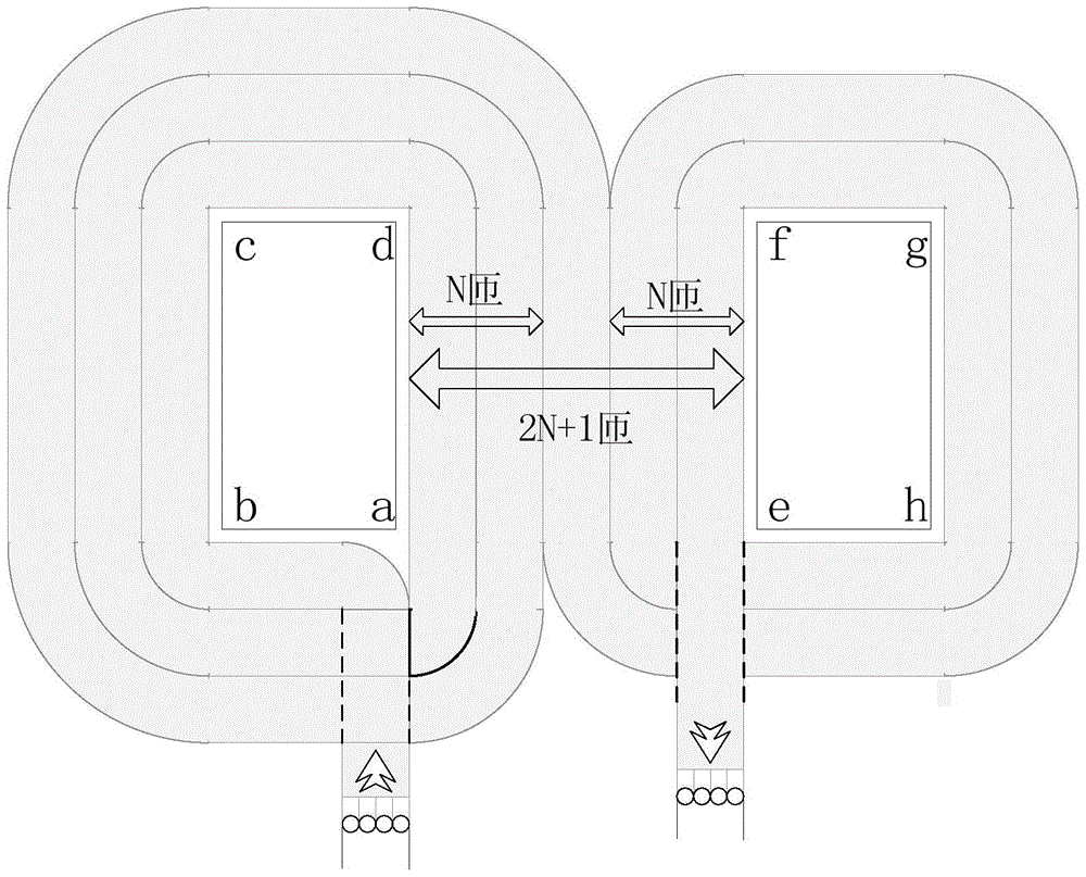
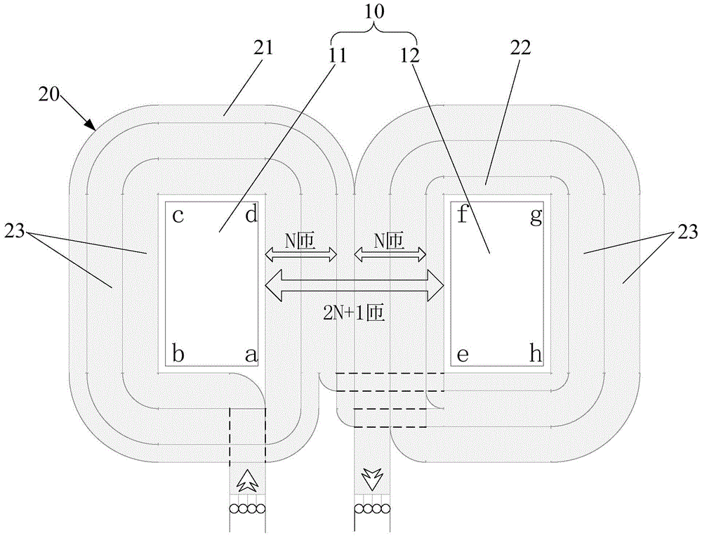
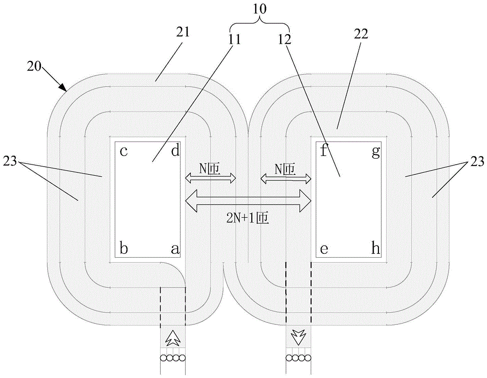
[0041] refer to Figure 2 to Figure 4 , figure 2 It is a structural schematic diagram of the first embodiment of the transformer coil of the present invention, image 3 It is a structural schematic diagram of the second embodiment of the transformer coil of the present invention, Figure 4 It is a structural schematic diagram of the third embodiment of the transformer coil of the present invention.

[0042] In one embodiment, the transformer coil includes a U-shaped magnetic core 10 and a wire 20, the U-shaped magnetic core 10 includes a first magnetic column 11 and a second magnetic column 12, and the wire 20 is composed of several sub-wires; The first magnetic column 11 and the second magnetic column 12 are coiled with the wire 20, and the sum of the turns of ...


PUM


Abstract

The invention discloses a transformer coil. The transformer coil includes a U-shaped magnetic core and a wire. The U-shaped magnetic core includes a first magnetic column and a second magnetic column. The wire is composed of several sub-wires; Wires are coiled on the columns, and the sum of the turns of the wires coiled on the first magnetic column and the second magnetic column is 2N+1 turns, wherein, N is a positive integer greater than or equal to zero; at least a part of one turn of the wire The wires form the first sub-conductors, and another part of the sub-conductors forms the second sub-conductors, and the first sub-conductors are coiled on the first magnetic column, and the second sub-conductors are coiled on the second magnetic column. The invention also discloses a transformer coil winding method and a transformer. When the sum of the turns of the wires coiled on the first magnetic column and the second magnetic column is an odd number of turns, it can effectively balance the coiled wires on the first magnetic column and the second magnetic column, so that the first magnetic column and the second magnetic column The number of turns of the wire coiled on the magnetic column is relatively consistent, which improves the coupling coefficient of the transformer.

Description

technical field [0001] The invention relates to the technical field of wireless charging, in particular to a transformer coil, a method for winding the transformer coil and a transformer. Background technique [0002] Wireless charging is a technology that transmits electric energy in the air between the charging device and the charged device through technologies such as electromagnetic induction, thereby charging the battery of the charged device. Compared with wired charging, wireless charging has the advantages of less leakage, fully automatic operation and unattended operation, so it has been widely used in electric vehicle charging technology. [0003] In the prior art, a secondary coil is installed on an electric vehicle, and a primary coil is installed on a parking space of a wireless charging system. When the electric vehicle is parked at the preset charging position on the parking space, the primary coil and the secondary coil form a loosely coupled transformer, an...

Claims


Application Information

Patent Timeline
Patent Type & Authority Patents(China)
IPC IPC(8): H01F27/30H01F27/28H01F41/06H01F41/069
Inventor 毛涛月刘玮周建平
Owner ZTEV
Why Eureka
Try Eureka