
Reactive voltage control method considering dynamic reactive power reserves of partitions
A voltage control method and a voltage control model technology, applied in reactive power compensation, AC network voltage adjustment, etc., can solve the problems of system reactive power reserve reduction, inability to ensure power grid partitions, etc.
- Summary
- Abstract
- Description
- Claims
- Application Information
AI Technical Summary
Problems solved by technology
Method used
Image

Examples
Embodiment Construction
[0040] The technical solution of the invention will be described in detail below in conjunction with the accompanying drawings.
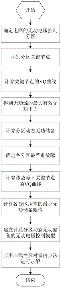
[0041] A reactive power and voltage control model and method involving dynamic reactive power reserves in the zones involved in the present invention, its algorithm flow is as follows figure 1 As shown, it includes the following 4 steps.
[0042] Step 1. Determine the reactive power and voltage control partitions of the power grid, and identify the key nodes of each partition:
[0043] Step 101, calculate the electrical distance d between the reactive source node and the controlled node ji :
[0044] d ji = - 1 g | Δ V j Δ V i | = - 1 g | ...
PUM
 Abstract
Description
Claims
Application Information