Eureka AIR delivers breakthrough ideas for toughest innovation challenges, trusted by R&D personnel around the world.

Power switch control system and method

A power switching and control system technology, applied in the direction of emergency power supply arrangements, electrical components, circuit devices, etc., can solve problems such as lack of initiative, affecting the stability of power supply voltage, and the failure of cars to start, achieving high efficiency and energy utilization. The effect of increasing flexibility and intelligence

Active Publication Date: 2015-06-10
XIAMEN YAXON NETWORKS CO LTD
View PDF5 Cites 6 Cited by
  • Summary
  • Abstract
  • Description
  • Claims
  • Application Information

AI Technical Summary

Problems solved by technology

[0003] 1. The tube consumption of the diode is large, there is a fixed voltage drop of about 0.7V, and it is greatly affected by the current and ambient temperature, which is easy to cause voltage drop drift and affect the stability of the power supply voltage
[0004] 2. When the external power supply and the backup battery exist at the same time, the power supply path of the backup battery can only be turned off after the system is started
[0005] 3. The traditional power switching system usually needs to automatically switch to the backup battery power supply after the external power supply is exhausted. Without initiative, this will make the car unable to start, and the car battery may be damaged after a long time

Method used


Image

  • Power switch control system and method

Examples


Embodiment

[0026] The present invention will be further described below through specific embodiments.

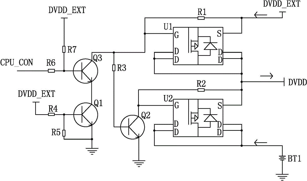
[0027] like figure 1 As shown, the present invention provides a power switching control system, including an external power output port DVDD_EXE, a backup battery output port BT1, a device power input port DVDD, a first PMOS transistor U1, a second PMOS transistor U2, and a first NPN triode Q1 and the second NPN transistor Q2;

[0028] The drain D of the first PMOS transistor U1 is connected to the source S of the second PMOS transistor U2 and connected to the power input port DVDD of the device; the source S of the first PMOS transistor U1 is connected to the source S of the second PMOS transistor U2 The drain D of U2 is respectively connected to the external power supply output port DVDD_EXE and the backup battery output port BT1; the gate G of the first PMOS transistor U1 is connected to the source S through a first resistor R1, and the second The gate G of the PMOS transistor U2 ...


PUM


Abstract

The invention discloses a power switch control system and method. The system comprises an external power supply output port, a standby battery output port, an equipment power supply input port, a first PMOS tube, a second PMOS tube, a first NPN triode and a second NPN triode, wherein the drain of the first PMOS tube is connected with the source of the second PMOS tube and is connected to the equipment power supply input port; the source of the first PMOS tube and the drain of the second PMOS tube are respectively connected with the external power supply output port and the standby battery output port; the grids of the first PMOS tube and the second PMOS tube are respectively connected with the collectors of the first NPN triode and the second NPN triode, and the grid of the first PMOS tube is connected with the base of the second NPN triode through a third resistor; the base of the first NPN triode is connected with the external power supply output port. The power switch control system is high in energy utilization rate.

Description

technical field [0001] The invention relates to an intelligent control system, in particular to a power switching control system and method. Background technique [0002] Due to various needs, some existing vehicle-mounted devices usually need to be powered all the time, such as GPS terminals, anti-theft devices, etc. When the car engine is not generating power, these on-board devices are usually powered by batteries. Therefore, when the car does not start for a long time, in order to prevent the power consumption of the battery from being exhausted, causing the car to fail to start, it is necessary to control the power consumption of the battery. One method is to put the on-board device into sleep mode or turn off the on-board device and then wake it up at regular intervals; the other method is to pass the power supply path of the on-board device to the battery (and the external power supply of the on-board device) before the battery power is lower than the car startup pre...

Claims


Application Information

Patent Timeline
IPC IPC(8): H02J9/06
Inventor 叶志聪肖振隆蔡炎平张航其吴振达蔡运文
Owner XIAMEN YAXON NETWORKS CO LTD
Why Eureka
Eureka Blog
Learn More