Control circuit applied to power adapter and operation method of control circuit
A power converter and control circuit technology, applied in the direction of output power conversion devices, electrical components, etc., can solve the problems of inaccurate judgment, high power consumption, and affecting the resonance frequency of auxiliary voltage Vaux
- Summary
- Abstract
- Description
- Claims
- Application Information
AI Technical Summary
Problems solved by technology
Method used
Image

Examples
Embodiment Construction
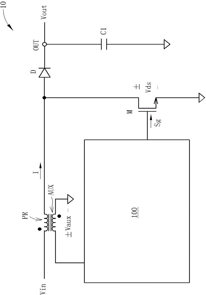
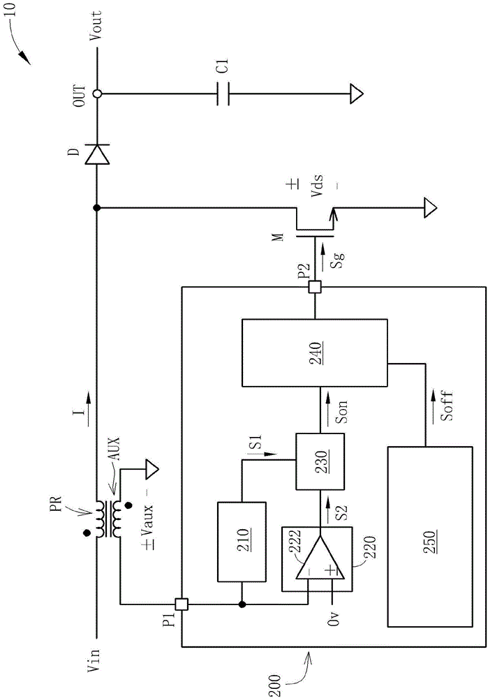
[0016] Please refer to image 3 , image 3 It is a schematic diagram of the first embodiment of the present invention applied to the control circuit of the power converter. Such as image 3 As shown, the power converter 10 includes a primary winding PR, an auxiliary winding AUX, a power switch M, a diode D, and a capacitor C1. The power switch M is coupled between the primary winding PR and the ground. The diode D and the capacitor C1 are coupled to the output terminal OUT. The control circuit 200 includes an auxiliary pin P1, a first detection unit 210, a second detection unit 220, a delay time controller 230, a gate signal generator 240, and a gate pin P2. The auxiliary pin P1 is used to receive the auxiliary voltage Vaux of the auxiliary winding AUX of the power converter 10 . The first detection unit 210 is used to detect a first time when the auxiliary voltage Vaux starts to resonate, and output a first detection signal S1 according to the first time. The second det...
PUM
 Abstract
Description
Claims
Application Information