Inkjet head driving method, inkjet head driving device, and inkjet printing device

A driving method and technology of a driving device, which can be applied in directions such as printing, can solve the problems of complicated ink supply system and difficult operation of heads, etc.

Active Publication Date: 2015-06-10
KONICA MINOLTA INC
View PDF9 Cites 11 Cited by
  • Summary
  • Abstract
  • Description
  • Claims
  • Application Information

AI Technical Summary

Problems solved by technology

In addition, there are also problems that as the number of rows of pressure chambers increases, the number of separati

Method used


Image

  • Inkjet head driving method, inkjet head driving device, and inkjet printing device
  • Inkjet head driving method, inkjet head driving device, and inkjet printing device
  • Inkjet head driving method, inkjet head driving device, and inkjet printing device

Examples


Embodiment 1

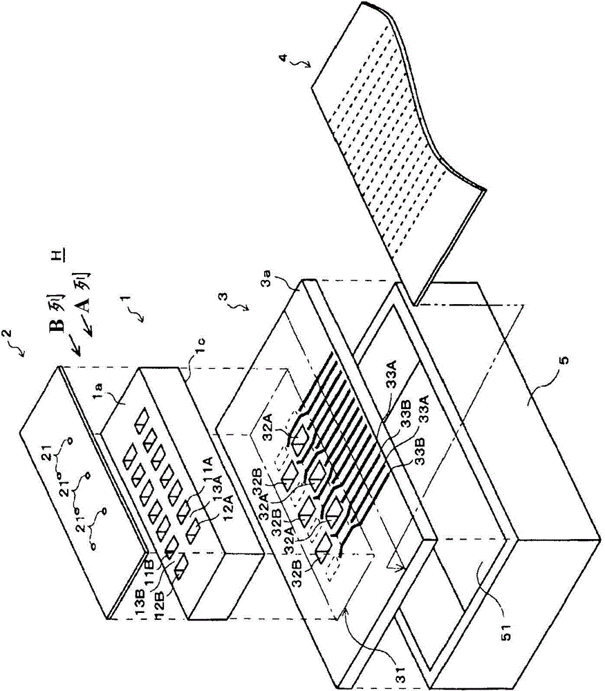
[0112] ready to have with figure 2 In an inkjet head having two channel rows having the same structure as the inkjet head shown, one channel row is used as drive group A, and the other channel row is used as drive group B. Each channel row has 256 nozzles, the distance D between the nozzles between the channel rows is 1.128 mm, and AL=5.0 μs.

[0113] The two channel columns of the inkjet head are driven by the same driving circuit.

[0114] The ink used for this inkjet head had a viscosity of 10 mPa·s, a surface tension of 32 mN / s, and a sound propagation speed in the ink of 1300 m / s.

[0115] According to the above conditions, the value of the pressure wave transmission time t obtained by "distance between nozzles between driving groups" / "speed of sound propagating in ink" is 1128 (μm) / 1300×10 6 (μm / s)=0.87×10 -6 (s) = 0.87 (μs), and here, t = 0.9 (μs) based on this calculated value.

[0116] The driving signal applied to each driving channel from the driving device use...

Embodiment 2

[0127] Crosstalk and driving load were evaluated in the same manner as in Example 1 except that the phase difference (nAL+t) was set to n=2, which was 2×5.0+0.9=10.9 μs. The results are shown in Table 1.

Embodiment 3

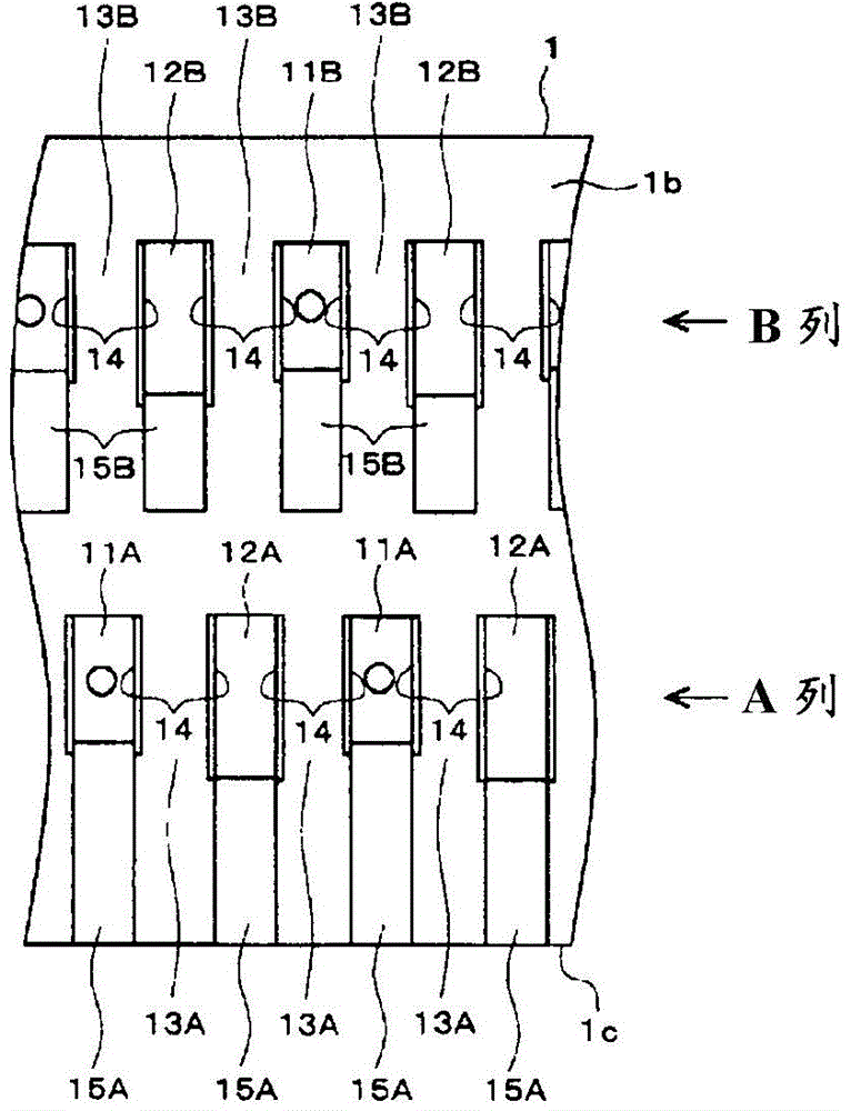
[0135] Prepare to list the nozzles of the inkjet head as Figure 11 In the inkjet head having four columns as shown, all channel columns are divided into two drive groups A and B so that the drive groups differ between adjacent channel columns. Each channel row has 256 nozzles, and the nozzle-to-nozzle distance D between the channel rows forming different drive groups is 0.846 mm, and AL=5.0 μs.

[0136] The four channels of the inkjet head are listed as Figure 15 The ground shown is driven by two drive circuits.

[0137] The ink used for this inkjet head had a viscosity of 5.7 mPa·s, a surface tension of 41 mN / s, and a sound propagation speed in the ink of 1600 m / s.

[0138] According to the above conditions, the value of the pressure wave propagation time t calculated by "the distance between the nozzles between the rows of adjacent pressure chambers" / "the speed at which sound propagates in the ink" is 846 (μm) / 1600×10 6 (μm / s)=0.53×10 -6 (s) = 0.53 (μs), and here, t ...


PUM

PropertyMeasurementUnit
Viscosityaaaaaaaaaa
Viscosityaaaaaaaaaa

Abstract

The purpose of the present invention is to provide an inkjet head driving method, an inkjet head driving device, and an inkjet printing device, which, without making any changes to head structure, can simultaneously reduce drive load and the crosstalk generated between multiple rows of pressure chambers that communicate through a common ink chamber. In an inkjet head comprising two or more rows of pressure chambers for generating the pressure to discharge the ink therein from the nozzles by means of pressure-supplying means that are operated by the application of drive signals and in which the pressure chambers of each row of pressure chambers communicate with each other through a common ink chamber: the rows of pressure chambers are divided into N (N being an integer 2 or greater) drive groups; and between different drive groups, a phase difference of nAL+t (n is an integer 1 or greater, AL is ½ of the acoustic resonance period of the pressure wave in the pressure chambers, and t is the pressure wave transmission time determined from [inter-nozzle distance between drive groups]/[velocity at which sound is conducted through the ink]) is provided for the drive signals that are applied to the pressure-supplying means of the pressure chambers.

Description

technical field [0001] The present invention relates to a driving method of an inkjet head, a driving device of an inkjet head, and an inkjet recording device. A driving method of an inkjet head, a driving apparatus of an inkjet head, and an inkjet recording apparatus affected by crosstalk in an inkhead. Background technique [0002] The inkjet head that generates pressure in the pressure chamber by the operation of the pressure applying means and discharges the ink in the pressure chamber from the nozzles is required to perform higher-speed and high-definition recording, and the number of nozzles and the number of nozzle rows tend to increase gradually. Along with this, the pressure wave generated in the pressure chamber at the time of discharge propagates to other pressure chambers, increasing the crosstalk that makes the droplet velocity (droplet volume) unstable, and increasing the driving load caused by simultaneously driving multiple pressure chambers. Big becomes a p...

Claims


Application Information

Patent Timeline
IPC IPC(8): B41J2/045B41J2/055
CPCB41J2/04543B41J2/04573B41J2/04581B41J2/14209B41J2002/14459
Inventor 小林谅平
Owner KONICA MINOLTA INC
Why Eureka
Try Eureka