Hand-held power tool

a technology of hand-held power tools and vibration-proofing structures, which is applied in the direction of manufacturing tools, portable power-driven tools, metal sawing devices, etc., can solve the problem of low effect of reducing vibration in the other direction, and achieve the effect of improving the effect of reducing vibration of the handle and improving workability

Inactive Publication Date: 2010-08-19
MAKITA CORP
View PDF9 Cites 24 Cited by
  • Summary
  • Abstract
  • Description
  • Claims
  • Application Information

AI Technical Summary

Benefits of technology

[0025]In a construction in which the grip part of the auxiliary handle can rotate in all directions (of z-, y- and x-axes) via the vibration-proofing part, when the grip part is acted upon by a force of rotation around its longitudinal direction or on the y-axis during operation of the hand-held power tool, the grip part may rotate on the y-axis with respect to the handle body. If such occurs, the operation gets hard. According to this invention, however, the rotation preventing mechanism can prevent the grip part from rotating on the y-axis with respect to the handle body, so that the workability can be improved.
[0026]According to this invention, a technique that contributes to further improvement of the effect of reducing vibration of a handle in a hand-held power tool is provided.

Problems solved by technology

According to such known vibration-proofing structure, however, the shearing direction of the elastic element is limited to the longitudinal direction of the power tool body or the horizontal direction and the vertical direction transverse to the longitudinal direction, so that the effect of reducing vibration in the other directions is low.

Method used


Image

  • Hand-held power tool
  • Hand-held power tool
  • Hand-held power tool

Examples


first embodiment

of the Invention

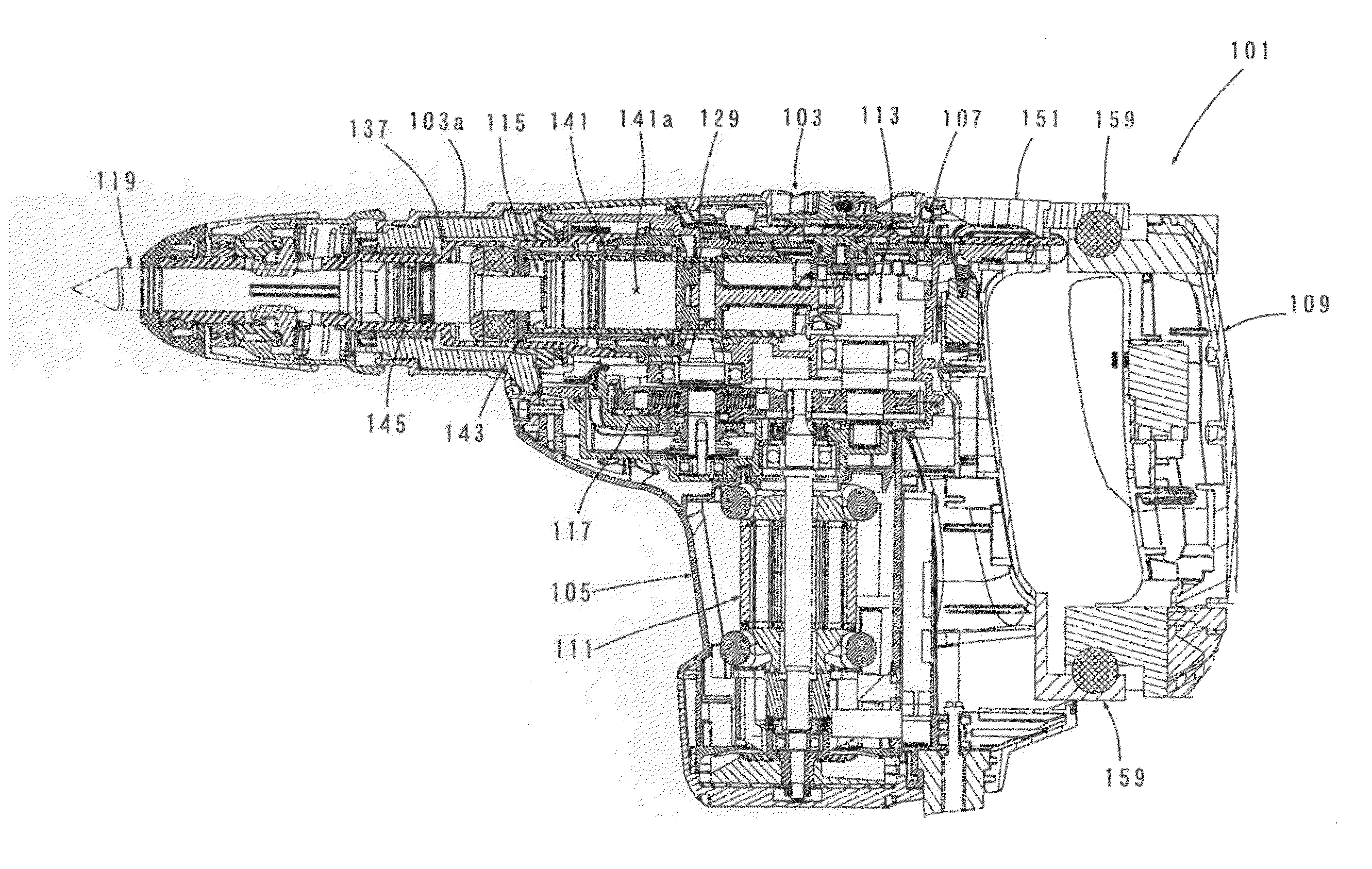
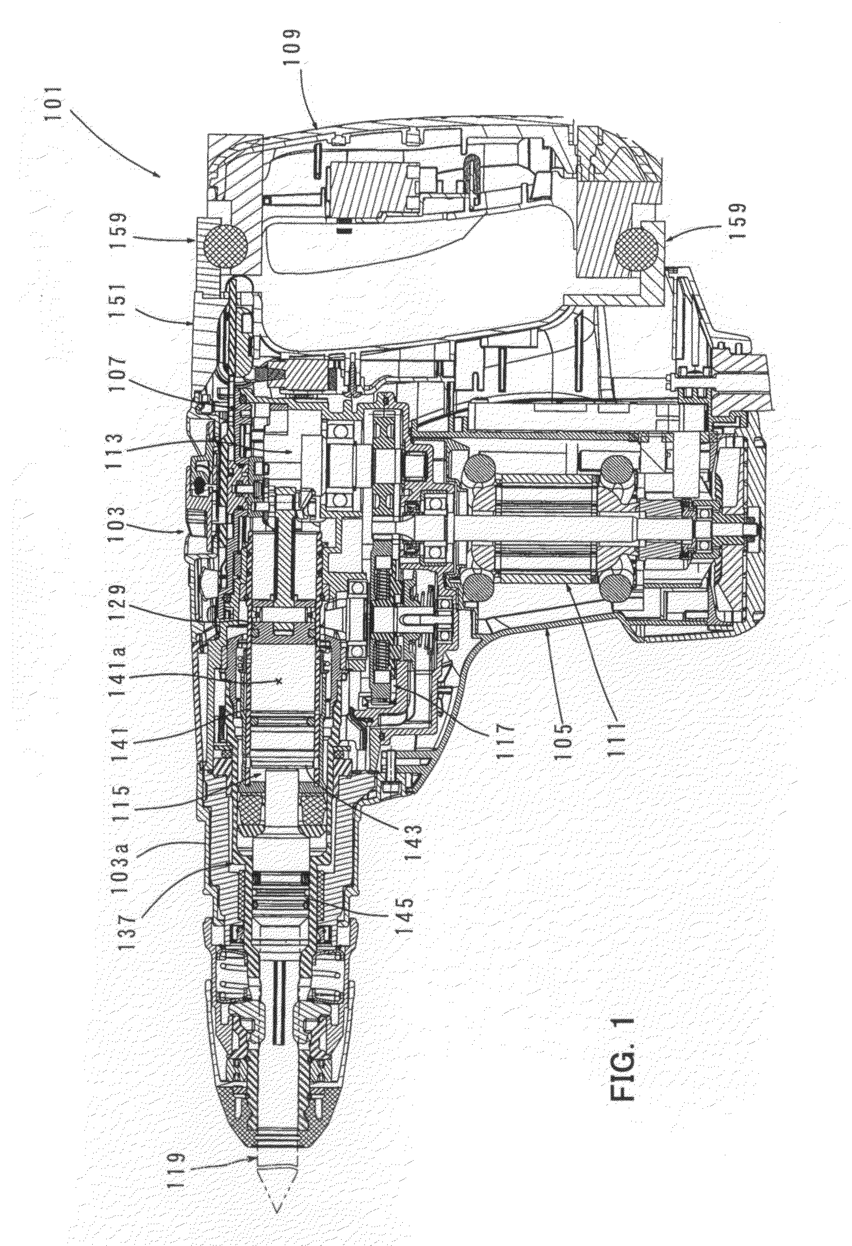
[0048]A first embodiment of the present invention is now described with reference to the drawings. FIG. 1 is a sectional side view showing an entire electric hammer drill 101 as a representative example of a hand-held power tool according to the present invention. As shown in FIG. 1, the hammer drill 101 of this embodiment includes a body 103 that forms an outer shell of the hammer drill 101, a hammer bit 119 detachably coupled to the tip end region (on the left side as viewed in FIG. 1) of the body 103 via a tool holder 137, and a handgrip 109 that is connected to the body 103 on the side opposite from the hammer bit 119 and designed to be held by a user. The body 103 and the hammer bit 119 are features that correspond to the “power tool body” and the “tool bit”, respectively, according to the present invention, and the handgrip 109 is a feature that corresponds to the “handle” and the “main handle” according to the present invention. The hammer bit 119 is held by t...

second embodiment

of the Invention

[0070]A second embodiment of the present invention is now described with reference to FIGS. 8 and 9. In the electric hammer drill according to the above-described first embodiment, in the case of the construction in which the handgrip 109 can move with respect to the covering member 151 (the body 103) via the vibration-proofing parts 159 in all directions (of z-, y- and x-axes), when the handgrip 109 is acted upon by a force of rotation around the longitudinal direction of the handgrip 109 or on the y-axis during operation, the handgrip 109 may rotate on the y-axis with respect to the covering member 151. If such a phenomenon occurs, the operation gets hard for the user.

[0071]Therefore, in the second embodiment, a torsion bar 161 is provided in order to prevent such rotation of the handgrip 109 on the y-axis. In the other points, it has substantially the same construction as the above-described first embodiment. Components which are substantially identical to those i...

third embodiment

of the Invention

[0076]A third embodiment of the present invention is now described with reference to FIGS. 10 and 11. This embodiment is a modification to the torsion bar 161 of the second embodiment. FIG. 10 is a vertical sectional view showing a D-shaped handle having the handgrip 109 connected to the covering member 151 via the upper and lower vibration-proofing parts 159, and FIG. 11 is a sectional view taken along line E-E in FIG. 10.

[0077]In this modification, the torsion bar 161 is formed by bending a round bar of spring material into a generally U-shape. The torsion bar 161 has the horizontally extending lower-side straight portion 161a and right and left vertical portions 161c extending straight upward from the ends of the lower-side straight portion 161a. The lower-side straight portion 161a is fitted in the mounting groove 153c of the covering-side rubber support 153, and the right and left vertical portions 161c are fitted in right and left vertically extending mounting ...


PUM

PropertyMeasurementUnit
angleaaaaaaaaaa
elasticaaaaaaaaaa
shearing stiffnessaaaaaaaaaa

Abstract

Improving vibration reduction of a handle in a hand-held power tool by performing a predetermined operation on a workpiece by linear movement of a tool bit in an axial direction. The power tool includes a power tool body, a handle and a vibration-proofing part. The vibration-proofing part includes an elastic element that is disposed between the power tool body and the handle and reduces transmission of vibration from the power tool body to the handle, and also includes a body-side receiving part and a handle-side receiving part which are opposed to each other so as to hold the elastic element. The vibration-proofing part is designed such that deformation of the elastic element is shearing deformation in each of the direction of a z-axis defined along the axial direction of the tool bit and the directions of a y-axis and an x-axis which intersect with the z-axis.

Description

FIELD OF THE INVENTION[0001]The present invention relates to a vibration-proofing structure of a handle in a hand-held power tool, such as a hammer and a hammer drill, which drives a tool bit to reciprocate in a constant cycle.BACKGROUND OF THE INVENTION[0002]According to a known hand-held power tool such as a hammer with a vibration-proof handle, the handle is connected to the power tool body via an elastic rubber, in order to reduce transmission of vibration from a power tool body to the handle. For example, Japanese non-examined laid-open Patent Publication No. 58-34271 discloses such a power tool. An elastic rubber has lower shearing stiffness compared with its compressive stiffness. Thus, it has a property that a higher vibration reducing effect can be obtained by shearing deformation than by compressive deformation. In the above-mentioned known power tool, transmission of vibration from a power tool body to a handle is reduced in the longitudinal direction of the power tool bo...

Claims


Application Information

Patent Timeline
Patent Type & Authority Applications(United States)
IPC IPC(8): B25D17/24B25D17/04
CPCB23D51/01B25D17/043B25D2211/003Y10T16/48B25D2250/321B25F5/026Y10T16/4713B25D2222/57B25D17/04B25D2211/068
Inventor KAMEGAI, HIKARUARAKAWA, TAKUO
Owner MAKITA CORP
Why Eureka
Try Eureka