Rotor assembly for electric machine and method for producing rotor assembly

A technology of rotors and components, which is applied in electric components, electrical components, centering/balancing rotors, etc., can solve the problems of heavy rotor weight, high moment of inertia of motors, and high cost, and achieve the effect of rotor weight

Active Publication Date: 2015-06-10
VTESCO TECH GMBH
View PDF7 Cites 12 Cited by
  • Summary
  • Abstract
  • Description
  • Claims
  • Application Information

AI Technical Summary

Problems solved by technology

It shows that this solution for balancing the rotor has the disadvantage that the rotor has to be provided before the additional weight material is selectively removed later, which overall results in a relatively heavy rotor weight and thus also in the electrical machine. high moment of inertia
[0007] Alternative, conceivable solutions for balancing rotors are very difficult and expensive for standardized or automated production processes by selectively adding weight material (for example by applying balancing paste to the rotor)

Method used


Image

  • Rotor assembly for electric machine and method for producing rotor assembly
  • Rotor assembly for electric machine and method for producing rotor assembly
  • Rotor assembly for electric machine and method for producing rotor assembly

Examples


Embodiment Construction

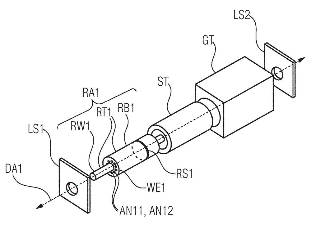
[0043] First, refer to figure 1 , in which an electric machine EM according to a first embodiment of the invention is shown in simplified and schematic form in an exploded view, said embodiment serving as a drive for, for example, a hybrid vehicle or an electric vehicle.

[0044] The electric machine EM comprises a housing part GT for receiving a stator ST, a stator ST, a rotor assembly RA1 together with a rotor shaft RW1 , and first and second end plates LS1 and LS2 for supporting and fixing the rotor shaft RW1 . In the fully assembled state of the electric machine EM, the housing part GT completely surrounds the stator ST and fixes it firmly in motion. The stator ST is of cylindrical design and has a cavity in which the rotor assembly RA1 in the fully installed state of the electric machine EM is supported rotatably and coaxially relative to the stator ST.

[0045] The electric machine EM or the rotor assembly RA1 has an axis of rotation DA1 about which the rotor assembly R...


PUM


Abstract

The invention relates to a rotor assembly (RA1, RA2) for an electric machine (EM), comprising a rotor (RT1, RT2) having an axis of rotation (DA1, DA2) extending in an axial direction of the rotor (RT1, RT2) and at least one first hole (AN11, AN12, AN21, AN21´, AN3) extending parallel to the axis of rotation (DA1, DA2) and radially spaced from the axis of rotation (DA1, DA2) by a first radial distance (A1, A21), and at least one first balancing element (WE1, WE21, WE3) for compensating an unbalance of the rotor (RT1, RT2) in rotation about the axis of rotation (DA1, DA2), wherein the at least one first balancing element (WE1, WE21, WE3) can be provided in the at least one first hole (AN11, AN12, AN21, AN21´, AN3) and can be fastened in the at least one first hole (AN11, AN12, AN21, AN21´, AN3) by means of a press fitting connection (PV) between the at least one first hole (AN11, AN12, AN21, AN21´, AN3) and the at least one first balancing element (WE1, WE21, WE3). Thus, a simple and economical possibility of balancing the rotor is provided.

Description

technical field [0001] The invention relates to a rotor assembly for an electric machine (or electric motor) and a method for producing the rotor assembly. Furthermore, the invention includes an electric machine having such a rotor assembly. Background technique [0002] Electric machines, especially those used to drive hybrid or electric vehicles, typically have a rotor that can often be accelerated to rotational speeds above 15,000 rpm (revolutions per minute) during operation of the electric machine. [0003] If a rotor rotating at such speeds becomes unbalanced, especially if the mass of the rotor is asymmetric about the axis of rotation of the rotor, this can lead to undesirable vibrations and increased wear on the motor. [0004] Therefore, in such machines, it is absolutely necessary to perform rotor balancing in order to reduce or avoid vibration or wear on the machine. [0005] It is conceivable to balance the rotor by selectively removing or adding weight materia...

Claims


Application Information

Patent Timeline
Patent Type & Authority Applications(China)
IPC IPC(8): H02K7/04H02K15/16
CPCH02K7/04H02K15/165
Inventor M.拉德魏因斯基
Owner VTESCO TECH GMBH
Why Eureka
Try Eureka