Ejector for soil deep placement

A sprayer and soil technology, applied in the field of deep soil application sprayer, can solve the problems of destroying the plowing layer, demanding foundation conditions, soil damage, etc., and achieve the effect of small soil compaction, high power requirements, and high degree of integration

Active Publication Date: 2015-06-17
CHENGDU TOBEST DIYUAN TECH CO LTD
View PDF5 Cites 33 Cited by
  • Summary
  • Abstract
  • Description
  • Claims
  • Application Information

AI Technical Summary

Problems solved by technology

[0002] Existing soil mechanized subsoiling technology is to use high-horsepower tractors to drive the plowshares to move laterally to loosen the soil, break the bottom of the plow, and deepen the plowing layer, while the deep application of silty fertilizers is to spread the fertilizer granules on On the surface of the ground, use a rotary tiller or tractor to rotate or plow into the soil. There is no mobile soil deep loosening and deep application related technology and complete sets of equipment
[0003] There are some technical deficiencies in the above subsoiling and deep fertilization methods. First, the technology is single and cannot be carried out in a complete set. Fertilization, soil loosening, and mobile silt fertilizer transportation are carried out separately, and integration has not been realized; second, the application range is small. It can only be applied to cultivated land with good conditions for large-scale cultivation in plains, and is not applicable to mountainous areas, hills, scattered plots and greenhouses; third, it is applicable to a single variety of crops, only applicable to annual field crops, and can do nothing for intertillage and loose soil of perennial economic crops; Fourth, it requires a lot of power and has strict requirements on the basic conditions. It needs to be driven by a large tractor, and the supporting conditions for the foundation are relatively high. Fifth, it has serious damage to the soil. Large-scale machinery can compact the soil and make it harden again. At the same time, the loosening of the soil may damage the soil. granule structure, thereby destroying the cultivated layer

Method used


Image

  • Ejector for soil deep placement
  • Ejector for soil deep placement

Examples


Embodiment Construction

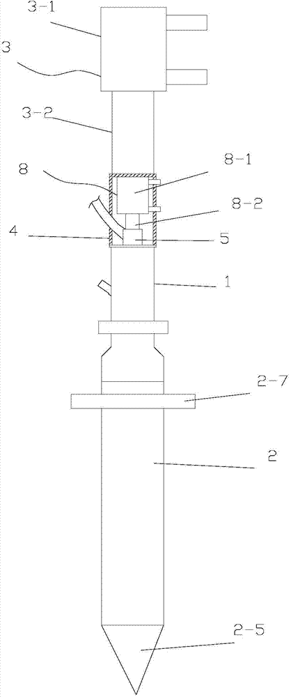
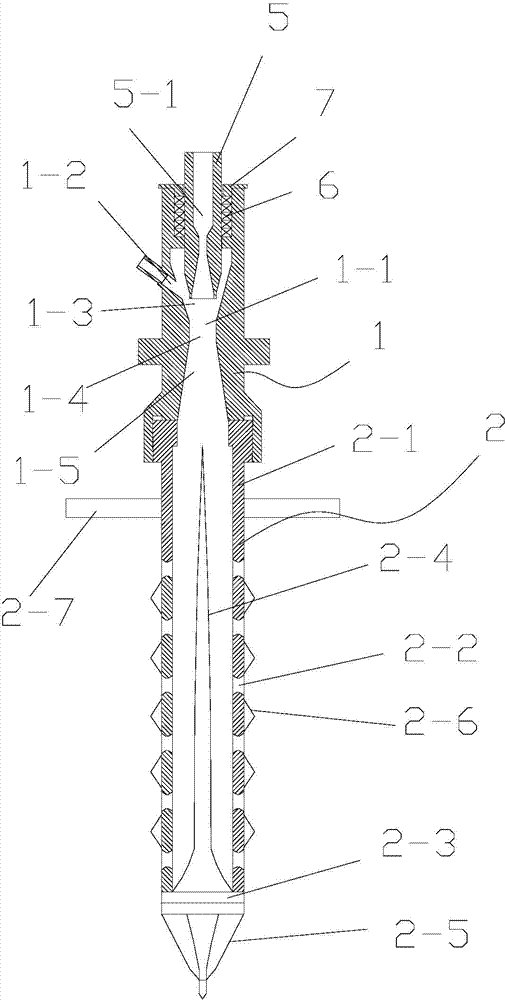
[0020] figure 1 It is a schematic diagram of the overall structure of the soil deep application injector of the present invention, figure 2 It is a longitudinal sectional view of the deep soil application injector of the present invention, as shown in the figure: the deep soil application injector of the present invention includes an air delivery device 1 for delivering high-pressure jet airflow, and the air flow delivery device 1 is provided with an air flow Channel 1-1 and fertilizer channel 1-2 for feeding fertilizer, the airflow channel 1-1 is a Venturi structure, and the fertilizer outlet of the fertilizer channel 1-2 communicates with the constriction area of ​​the airflow channel 1-1 ; Because the airflow channel 1-1 is a Venturi structure, as shown in the figure, the airflow channel 1-1 of the Venturi structure includes a constriction zone 1-3, a weir zone 1-4 and an expansion zone 1-5, because the expansion zone pressure is higher At the bottom, the high-pressure je...


PUM


Abstract

The invention discloses an ejector for soil deep placement. The ejector comprises an airflow conveyer for conveying high-pressure jet airflow, wherein an airflow channel and a fertilizer channel for feeding a fertilizer are arranged in the airflow conveyer; the airflow channel is in a venturi structure; a fertilizer outlet of the fertilizer channel is communicated with a shrinkage area of the airflow channel; and the airflow conveyer is used for conveying the high-pressure jet airflow. The airflow channel is in the venturi structure, and can play an accelerating role in the flowing airflow; meanwhile, the fertilizer channel and the fertilizer outlet of the fertilizer channel are communicated with the shrinkage area of the airflow channel; and negative-pressure material suction is formed on a powder fertilizer by the high-pressure jet airflow flowing through the airflow channel, so that the powder fertilizer is mixed with the high-pressure je airflow in the airflow channel to enter soil along with the high-pressure je airflow, and thus the target of the deep placement is reached.

Description

technical field [0001] The invention relates to the field of deep loosening of soil, in particular to a sprayer for deep application of soil. Background technique [0002] Existing soil mechanized subsoiling technology is to use high-horsepower tractors to drive the plowshares to move laterally to loosen the soil, break the bottom of the plow, and deepen the plowing layer, while the deep application of silty fertilizers is to spread the fertilizer granules on On the ground surface, use a rotary tiller or tractor to rotate or plow into the soil. There is no mobile soil deep loosening and deep application related technology and its complete set of equipment. [0003] There are some technical deficiencies in the above subsoiling and deep fertilization methods. First, the technology is single and cannot be carried out in a complete set. Fertilization, soil loosening, and mobile silt fertilizer transportation are carried out separately, and integration has not been realized; seco...

Claims


Application Information

Patent Timeline
Patent Type & Authority Applications(China)
IPC IPC(8): A01C15/04A01C15/02
Inventor 吴福成李涛高伟孙兵
Owner CHENGDU TOBEST DIYUAN TECH CO LTD
Why Eureka
Try Eureka