
Hot rolling width model fast dynamic self-adapting method

A dynamic self-adaptive, width technology, applied in the direction of metal rolling, metal rolling, rolling mill control devices, etc., can solve the problems of not being able to eliminate width control deviation and low precision of strip width control

Active Publication Date: 2015-06-17
SHANGHAI MEISHAN IRON & STEEL CO LTD
View PDF6 Cites 8 Cited by
  • Summary
  • Abstract
  • Description
  • Claims
  • Application Information

AI Technical Summary

Problems solved by technology

[0006] 2) Intelligent learning system and calculation and learning method of hot-rolled strip width control model, patent number CN201110152867.5; this patent corrects the feedback values ​​of the rough rolling exit width gauge and the finish rolling width gauge, which is the existing technology. Different from the technical method of this patent application
[0010] None of the technical solutions disclosed above can eliminate the problem of width control deviation under high-speed rolling rhythm, and the subsequent strip width control accuracy is not high

Method used


Image

  • Hot rolling width model fast dynamic self-adapting method
  • Hot rolling width model fast dynamic self-adapting method
  • Hot rolling width model fast dynamic self-adapting method

Examples


Embodiment 1

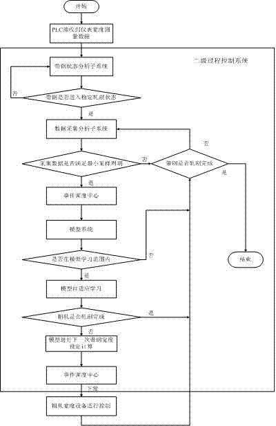
[0039] see figure 1 , a hot rolling width model fast dynamic adaptive method, the method includes the following steps, 1) after the strip passes through the equipment in the finishing rolling area and the width instrument at the exit of the finishing mill, the instrument detects the strip width, and then the instrument The detection cycle sends the corresponding width data to the first-level PLC system;

[0040] 2) After receiving the instrument data, the first-level PLC system sends the corresponding measurement width data to the second-level process control system with a fixed communication cycle;

[0041] 3) The strip status subsystem in the secondary process control determines the length of the strip entering stable rolling and the minimum sampling period according to the distance between the two stands, the thickness of the intermediate billet, the thickness of the finished product, and the rolling speed of the last stand ; The calculation method in this step is as follo...

Embodiment 2

[0057] Strip A, when the head of the strip passes through the Width instrument, it sends data to the PLC system, and the PLC sends the corresponding width data to the secondary process control system, and the secondary strip status subsystem determines the stable rolling of the strip according to the formula (1). The measurement length is 55 meters, and the minimum sampling period determined by the formula (2) is 5.5 seconds, such as image 3 As shown, the first data collection is completed. The rolling stable area is 55 meters and the minimum data collection period is 5.5 seconds. Since the rolling speed is 10m / s at a constant speed, the minimum detection cycle length is also 55 meters. Assuming that the instrument The sampling period is 0.1 second, and the minimum data collection volume is determined to be 55 sampling points. After the data collection system checks the data, the average value is calculated assuming that the average width is 1280mm. After the model receives th...


PUM


Abstract

The invention relates to a hot rolling width model fast dynamic self-adapting method. According to the main control principle of the hot rolling width model fast dynamic self-adapting method, the model leaning strategy is changed, the data collecting method is improved, one time of model self-adapting leaning is conducted through width detecting equipment needed the overall pass through of a strip steel formerly, and the methods that leaning is conducted when part of the strip steel passes through the width detecting equipment, and repeatedly dynamic learning strategy is possessed are replaced. The hot rolling width model fast dynamic self-adapting method have the advantages that the problems that the width self-adapting correction is lagged in real production control, the phenomenon of width over-control occurs, and the width control deviation occurs in high-speed rolling pacing are solved, and the subsequent strip steel control precision is improved.

Description

technical field [0001] The invention relates to an adaptive learning method, in particular to a fast and dynamic adaptive method for a hot-rolling width model, which belongs to the technical field of hot-rolling production control. Background technique [0002] At present, the width model adaptive method at home and abroad mainly uses the width measuring instrument equipment after the rolling mill to carry out width adaptive control. The main principle is that when a piece of hot-rolled strip A completely passes through the on-site instrument, the instrument samples the entire width data, and Submit the sampled feedback data of the strip control situation to the process control model system through the PLC, and the process control model system performs width correction control calculation on the next piece of strip B according to a certain algorithm, and sends it to the corresponding equipment for control. The purpose of correcting the width of the next rolled strip is achi...

Claims


Application Information

Patent Timeline
IPC IPC(8): B21B37/22
CPCB21B37/22
Inventor 盛磊孙建林李杰张健民尚雯金尧成钱正顺高媛李美华
Owner SHANGHAI MEISHAN IRON & STEEL CO LTD
Learn More