
Spinning machine spindle structure

A spinning machine and spindle technology, applied in the field of spinning machine spindle structure, can solve the problems of insufficient longitudinal load and longitudinal rigidity of the spindle, short life, etc., and achieve the effect of strong rigidity, large thrust and reduced stroke

Pending Publication Date: 2021-10-08
WUHAN HEAVY MACHINE TOOL GRP
View PDF7 Cites 0 Cited by
  • Summary
  • Abstract
  • Description
  • Claims
  • Application Information

AI Technical Summary

Problems solved by technology

In most existing machine tool spindle box structures, the longitudinal load and longitudinal rigidity of the spindle are not rigid enough, and the service life is short

Method used


Image

  • Spinning machine spindle structure

Examples


Embodiment Construction

[0015] The present invention will be further described below in conjunction with the accompanying drawings and specific embodiments.

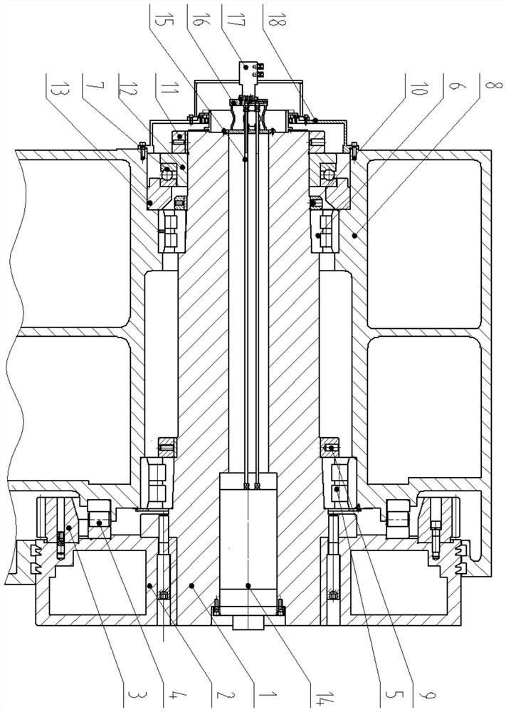
[0016] Such as figure 1 The spindle structure of a spinning machine shown includes a spindle 1, a faceplate 2, a ring gear 3, a box body 8, and a bearing. The back of the faceplate 2 is connected with a ring gear 3, a thrust roller bearing 4 is provided between the back of the faceplate 2 and the box body 8, the main shaft 1 is connected with the box body 8 through several double-row cylindrical roller bearings, and the tail end of the main shaft 1 is set There is a thrust ball bearing 7, which is fixed by a washer and a lock nut 11 at the tail end. The thrust ball bearing 7 is installed at the end of the main shaft through the washer 12 and the lock nut 11, and together with the washer 13 constrains the axial freedom of the main shaft. The afterbody is equipped with a support, and the rotary joint 17 is installed on the support 16, and commu...


PUM


Abstract

The invention discloses a spinning machine spindle structure which comprises a spindle, a faceplate, a gear ring, a box body and bearings. The spindle is installed in the box body, the faceplate is arranged at the front end of the spindle, the gear ring is connected to the back face of the faceplate, a thrust roller bearing is arranged between the back face of the faceplate and the box body, the spindle is connected with the box body through a plurality of double-row cylindrical roller bearings, a thrust ball bearing is arranged at the tail end of the spindle and fixed through a gasket and a tail end locking nut, the spindle is of a hollow structure, an ejection oil cylinder is installed in the spindle, and oil is supplied to the ejection oil cylinder through a rotary connector at the tail of the spindle, a piston rod can stretch out and retract, a support is arranged at the tail of the spindle, the rotary connector is connected onto the support, and the rotary connector is communicated with the ejection oil cylinder through an oil pipe. The structure has high rigidity and high bearing capacity.

Description

technical field [0001] The invention belongs to the field of spinning machine equipment, and in particular relates to a spinning machine spindle structure. Background technique [0002] Spinning forming technology is an advanced forming technology, which integrates extrusion, stamping, ring rolling, cross rolling, forging, rolling and other processes, and is an advanced process with less cutting and no cutting. [0003] The spinning machine can complete the spinning of cylindrical parts and curved generatrix parts. It is widely used in the aerospace field and is mainly used for processing rocket engine shells, heads and other parts. In the spinning machine tool, the spinning force is divided into vertical and horizontal. Based on the coordinates of the machine tool, the horizontal spinning force will generally be balanced as much as possible in the design of the machine tool, and the longitudinal spinning force will directly act on the machine tool spindle box through the mo...

Claims


Application Information

Patent Timeline
IPC IPC(8): B21D22/16B30B15/00
CPCB21D22/16B30B15/00Y02P70/62
Inventor 何发诚张召杰陈昳周建杰邢峰王俊夏天
Owner WUHAN HEAVY MACHINE TOOL GRP
Learn More