
Exhaust device for decorating machine

A technology for an exhaust device and a printing machine, which is used in printing machines, printing machines, general parts of printing machines, etc., can solve the problems of limited ventilation, increase production costs, and discomfort for operators, and achieve uniform and exhausting effects of absorbing oil fume and hot air. Good, smooth internal ventilation effect

Active Publication Date: 2015-06-17
王卫霞
View PDF9 Cites 1 Cited by
  • Summary
  • Abstract
  • Description
  • Claims
  • Application Information

AI Technical Summary

Problems solved by technology

Existing printing machines for paper and cloth generate a lot of heat while drying. On the one hand, a large part of the heat is lost to the outside, which is not conducive to drying, and also causes the indoor temperature to be too high, and the printing machine room cannot be large. The area is ventilated to prevent external dust from falling on the printing materials and affect the printing effect. Therefore, the ventilation is limited, the indoor temperature is high, and the operators are very uncomfortable. Therefore, air conditioners must be used. While high-power heat is generated, high-power refrigeration equipment is required to ensure indoor The temperature will not be too high, which will greatly waste electric energy and increase the production cost; in addition, while drying the ink, a large amount of ink gas will be emitted into the indoor air, causing great physical harm to the production personnel

Method used


Image

  • Exhaust device for decorating machine
  • Exhaust device for decorating machine
  • Exhaust device for decorating machine

Examples


Embodiment Construction

[0026] The present invention is described in detail below in conjunction with accompanying drawing:

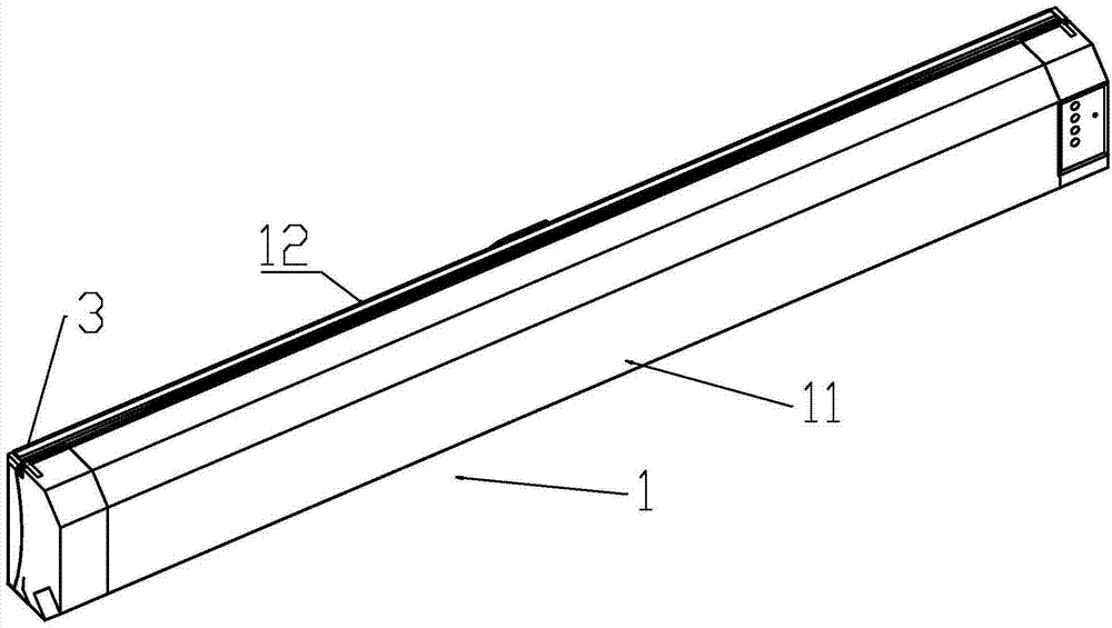
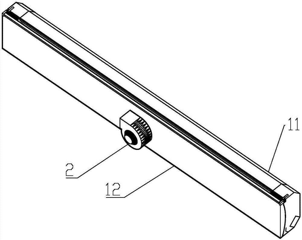
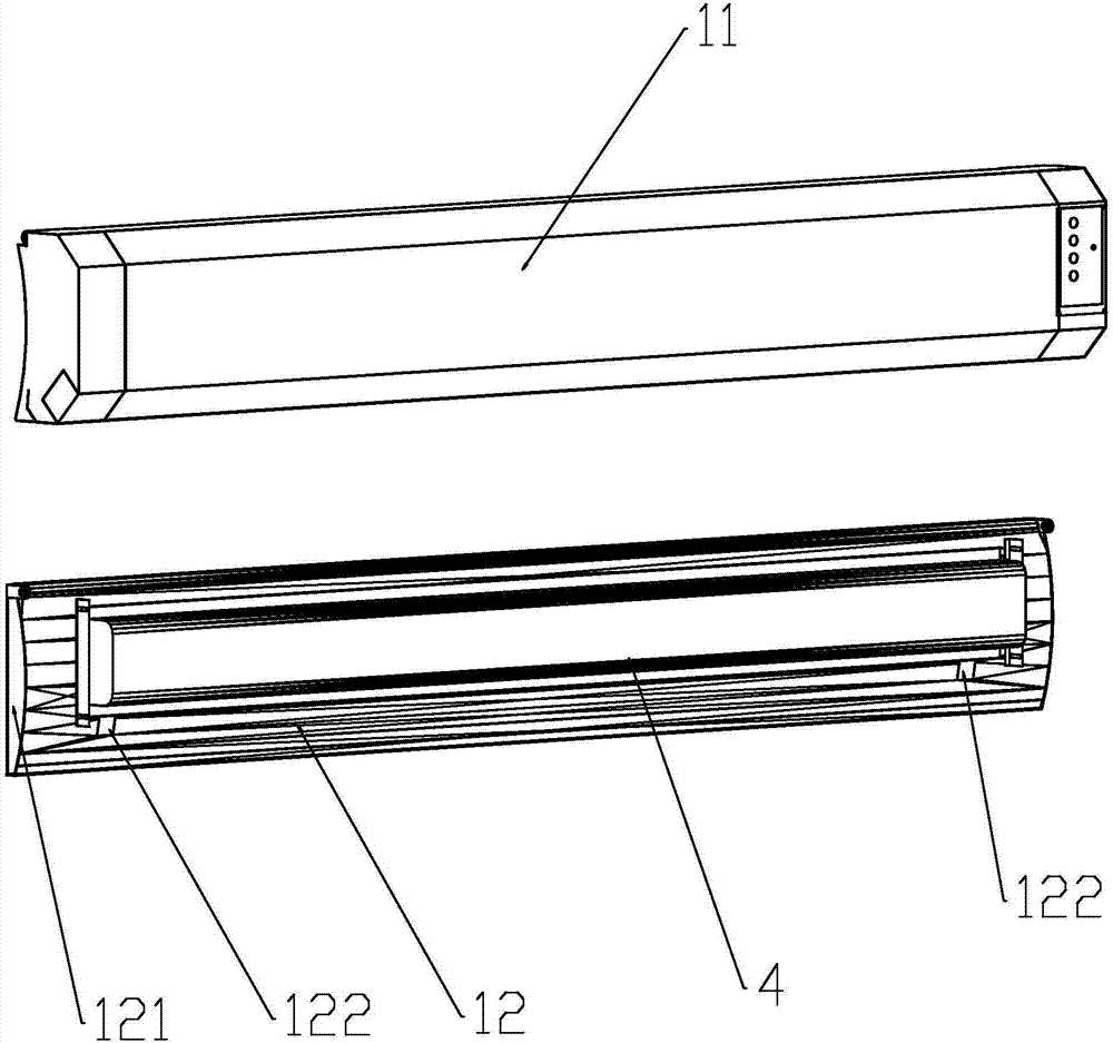
[0027] As shown in the figure, an exhaust device for a printing machine is applied to the subsequent drying step of the printing machine, and includes a cover body 1 covering the drying part 4 of the printing machine. There is a gap for printing sheets such as paper or cloth to pass through. The printing sheets enter from the upper end and pass through the lower end after being dried by the drying part. The exhaust fan 2 for extracting oil fume is connected to the cover body 1 . The exhaust fan 2 is arranged at the rear of the cover body 1 . The exhaust fan 2 discharges the heat and ink to the outside through the pipeline, so as to prevent the indoor high temperature and ink gas from harming the body and endangering health.

[0028] The cover body 1 includes a front cover 11 and a rear cover 12 , the upper parts of the front cover 11 and the rear cover 12 are connected by a ...


PUM


Abstract

The invention relates to an exhaust device for a decorating machine. The exhaust device comprises a cover covering a drying component of the decorating machine, clearances allowing a printing sheet to penetrate are formed in the upper portion and the lower portion of the cover, and a draft fan for pumping out ink smoke, heat and steam is connected with the cover. The exhaust device of the structure comprises the cover covering the drying component of the decorating machine, the cover is connected with the draft fan for pumping out the ink smoke, the heat is prevented from being dissipated into a room, drying quality is improved, the situation that the heat is dissipated into the room, consequently, indoor temperature is too high, high-power cooling equipment has to be mounted, and electric energy is wasted is avoided, the effect of saving energy is achieved, and production cost is saved. Ink gas generated in the drying process and other gas harmful to the human body are pumped out by the draft fan, and exhausted outdoors, work environment is improved, the bodies of production personnel are prevented from being injured, and the function of environmental protection is achieved. The steam generated in the drying process is pumped away, humidity in the cover is reduced, and the drying effect is better.

Description

【Technical field】 [0001] The invention relates to a device for a printing machine, in particular to an exhaust device for a printing machine. 【Background technique】 [0002] The printing machine is suitable for printing on various materials, printing ink on plastic, acrylic, metal, wood products, PVC, textile fabrics, glass, crystal, coated paper, ceramic tiles / porcelain, sportswear, household items, personalized patterns, textile fabrics, It can be used in a wide range of travel bags, advertising performances, umbrella advertisements, toy cushions, etc. After printing, it must be dried before it can be retracted, so as to avoid the ink after printing. Existing printing machines for paper and cloth generate a lot of heat while drying. On the one hand, a large part of the heat is lost to the outside, which is not conducive to drying, and also causes the indoor temperature to be too high, and the printing machine room cannot be large. The area is ventilated to prevent extern...

Claims


Application Information

Patent Timeline
IPC IPC(8): B41F23/04
Inventor 巫向东黄浩明
Owner 王卫霞
Learn More