Electric energy assisted braking system with complete coupling function between fraction braking and regenerative braking

A technology of electric power assist and regenerative braking, which is applied in electric braking systems, electric vehicles, transportation and packaging, etc., and can solve problems such as high manufacturing costs, difficulty in obtaining failure protection capabilities from car manufacturers, and high manufacturing costs of brake-by-wire systems , to achieve the effects of small system pressure fluctuations, reduced manufacturing costs, and high pressure regulation accuracy

Inactive Publication Date: 2015-06-17
JILIN UNIV
View PDF4 Cites 36 Cited by
  • Summary
  • Abstract
  • Description
  • Claims
  • Application Information

AI Technical Summary

Problems solved by technology

This type of braking system requires a complex mechanical conversion structure to generate braking force. Although the response speed is fast, because there is no hydraulic circuit in the system, an additional failure backup mechanism is required. At the same time, the system requires four motors and a high-performance power supply. , high manufacturing costs, for these reasons, EMB has not been applied in mass-produced cars so far
[0005] Therefore, from the perspective of matching the regenerative braking function of new energy vehicles, the brake-by-wire system can realize the complete decoupling of ...

Method used


Image

  • Electric energy assisted braking system with complete coupling function between fraction braking and regenerative braking

Examples


Embodiment Construction

[0030] The technical solution of the present invention will be described in detail below in conjunction with the accompanying drawings.

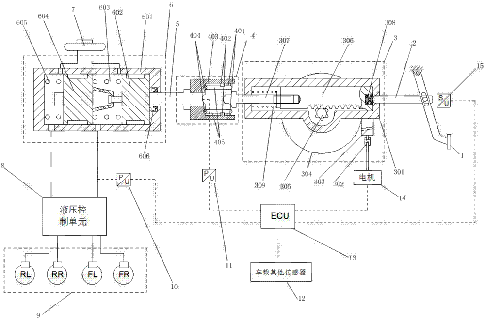
[0031] Such as figure 1 As shown, the electric power assist braking system with the complete decoupling function of friction braking and regenerative braking includes brake pedal 1, push rod 2, electric power assist assembly 3, electromagnet connector 4, master cylinder push rod 5, Master cylinder 6, liquid storage tank 7, hydraulic control unit 8, wheel cylinder 9, master cylinder pressure sensor 10, force sensor 11, other on-board sensors 12, electronic control unit (ECU) 13, motor 14, pedal displacement sensor 15.

[0032]The brake pedal 1 is connected to the push rod 2 through the support pin, the push rod 2 is connected to the rack and pinion mechanism of the electric power booster assembly 3, the motor 14 is connected to the worm gear mechanism of the electric power booster assembly 3, and the electric power booster assembly 3 and An ...


PUM


Abstract

The invention discloses an electric energy assisted braking system with a complete decoupling function between the fraction braking and the regenerative braking. When braking energy of a new energy vehicle is recycled, the friction braking force and the regenerative braking force can be decoupled completely, the energy can be recovered to the maximum extent, and electric braking power-assisted function and active braking function are possessed. The electric energy assisted braking system comprises a brake pedal, a push rod, an electric power-assisted assembly, an electromagnet connector, a master cylinder push rod, a master cylinder, a fluid reservoir, a hydraulic control unit, sensors and a motor; the brake pedal is connected with the push rod through a rest pin, the master cylinder and the hydraulic control unit are communicated through braking lines, and the motor, the hydraulic control unit and the sensors are all connected with an electronic control unit in a vehicle; the electromagnet connector is arranged between the electric power-assisted assembly and the master cylinder, and the front end of the electromagnet connector is connected with the master cylinder push rod in a contacting mode; a rack of the electric power-assisted assembly is connected with the push rod is a contacting mode, a pressure rod is coaxially arranged with the master cylinder push rod, a gap is reserved between the pressure rod and the master cylinder push rod, and the pressure rod and the master cylinder are connected through a worm.

Description

technical field [0001] The invention belongs to the technical field of automobile braking systems, and in particular relates to an electric power-assisted braking system with a complete decoupling function of friction braking and regenerative braking. Background technique [0002] With the development of automobile technology, new energy vehicles have entered the stage of history. Compared with traditional vehicles, new energy vehicles use motors as the core drive components. Therefore, the drive motor can be converted into a generator when braking. , to convert the kinetic energy of the vehicle into electrical energy to achieve energy recovery. [0003] At present, most automobile hydraulic braking systems use vacuum power assist, and a few cars use other forms of power assist devices such as electric power assist (such as the e-ACT braking system of Nissan Motor Company). The vacuum booster needs the engine to cooperate with the pumping vacuum. Therefore, if the braking s...

Claims


Application Information

Patent Timeline
IPC IPC(8): B60L7/10B60L7/24
Inventor 何睿邓伟文吴坚刘海贞孙文龙
Owner JILIN UNIV
Why Eureka
Try Eureka