Portable type heat pipeline detection device
A technology for thermal pipelines and detection devices, applied in pipeline systems, mechanical equipment, gas/liquid distribution and storage, etc., can solve problems such as increasing the difficulty of excavation, accurate basis, and inability to use it as a leak point to determine the leakage point, etc. Maintenance and normal use, simple structure, small size effect
- Summary
- Abstract
- Description
- Claims
- Application Information
AI Technical Summary
Problems solved by technology
Method used
Image
Examples
Embodiment 1
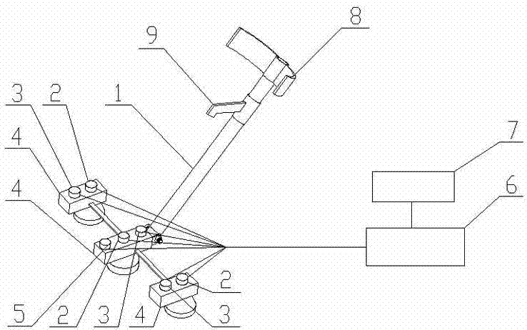
[0024] Such as figure 1 As shown, the portable thermal pipeline detection device of the present invention includes a rod body 1 and a data acquisition box 6. One end of the rod body 1 is hinged with a sensor bracket, and a micro-magnetic sensor 2, an infrared temperature sensor 3 and a humidity sensor 5 are arranged on the sensor bracket. 2. Both the infrared temperature sensor 3 and the humidity sensor 5 are connected to the data collection box 6 through wires. The data acquisition box 6 is connected to a controller 7 through wires. There is an arm ring 8 at one end of the rod body 1 away from the sensor bracket, and a handle 9 is provided at a position close to the arm ring 8 on the rod body 1 .
[0025] In this embodiment, the sensor bracket includes three rod-shaped supports 4, the three supports 4 are arranged in parallel and side by side, and the adjacent supports 4 are connected by cross bars, that is, the three supports 4 Centerlines are in the same plane. Each supp...
Embodiment 2
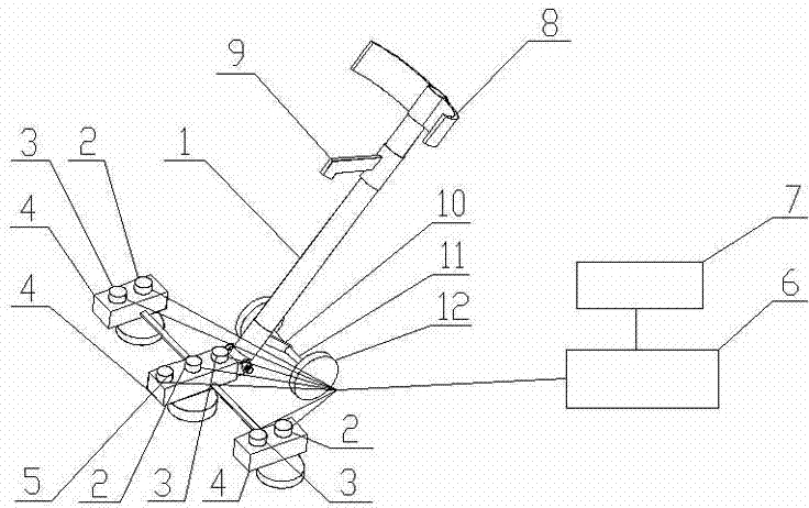
[0029] Such as figure 2 As shown, the main structure of the portable thermal pipeline detection device of this embodiment is the same as that of Embodiment 1, and will not be described in detail here. The difference is that the shaft support 10 is fixed on the rod body 1 on the lower side of the hinge point, and the shaft support 10 has a wheel shaft 11.
[0030] When in use, hold the handle 9 of the portable thermal pipeline detection device with your hand, and make the arm ring 8 drag the arm of the hand, pick up the device or push the device to move. The data acquisition box 6 and the controller 7 can be carried by other auxiliary facilities, or can be directly hung or carried on the operator's body. Start the power supply so that the probes of each sensor are aligned with the road surface corresponding to the thermal pipeline to be tested. When the operator walks along the direction of the thermal pipeline arrangement, each sensor can collect the corresponding data. ...
Embodiment 3
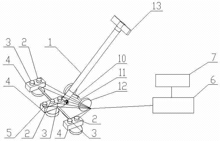
[0033] Such as image 3 As shown, the portable thermal pipeline detection device of the present invention includes a rod body 1 and a data acquisition box 6. One end of the rod body 1 is hinged with a sensor bracket, and a micro-magnetic sensor 2, an infrared temperature sensor 3 and a humidity sensor 5 are arranged on the sensor bracket. 2. Both the infrared temperature sensor 3 and the humidity sensor 5 are connected to the data collection box 6 through wires. The data acquisition box 6 is connected to a controller 7 through wires. The shaft support 10 is fixed on the rod body 1 on the lower side of the hinge point, and the other end of the rod body 1 has a handrail 13 . A wheel shaft 11 is arranged on the wheel shaft support 10 , the axis of the wheel shaft 11 is perpendicular to the axis of the rod body 1 , and rollers 12 are arranged at both ends of the wheel shaft 11 .
[0034] In this embodiment, the number and layout of the support 4 on the sensor bracket and the sen...
PUM
 Abstract
Description
Claims
Application Information
 - R&D
- Intellectual Property
- Life Sciences
- Materials
- Tech Scout
- Unparalleled Data Quality
- Higher Quality Content
- 60% Fewer Hallucinations
Browse by: Latest US Patents, China's latest patents, Technical Efficacy Thesaurus, Application Domain, Technology Topic, Popular Technical Reports.
© 2025 PatSnap. All rights reserved.Legal|Privacy policy|Modern Slavery Act Transparency Statement|Sitemap|About US| Contact US: help@patsnap.com


