

Methane gas recycling system and recycling control method
A recovery system and control method technology, applied in the field of gas recovery and reuse, can solve problems such as hidden safety hazards, high cost, and low efficiency, and achieve the effects of saving labor costs and reducing ineffective power costs
- Summary
- Abstract
- Description
- Claims
- Application Information
AI Technical Summary
Problems solved by technology
Method used
Image


Examples
Embodiment 1
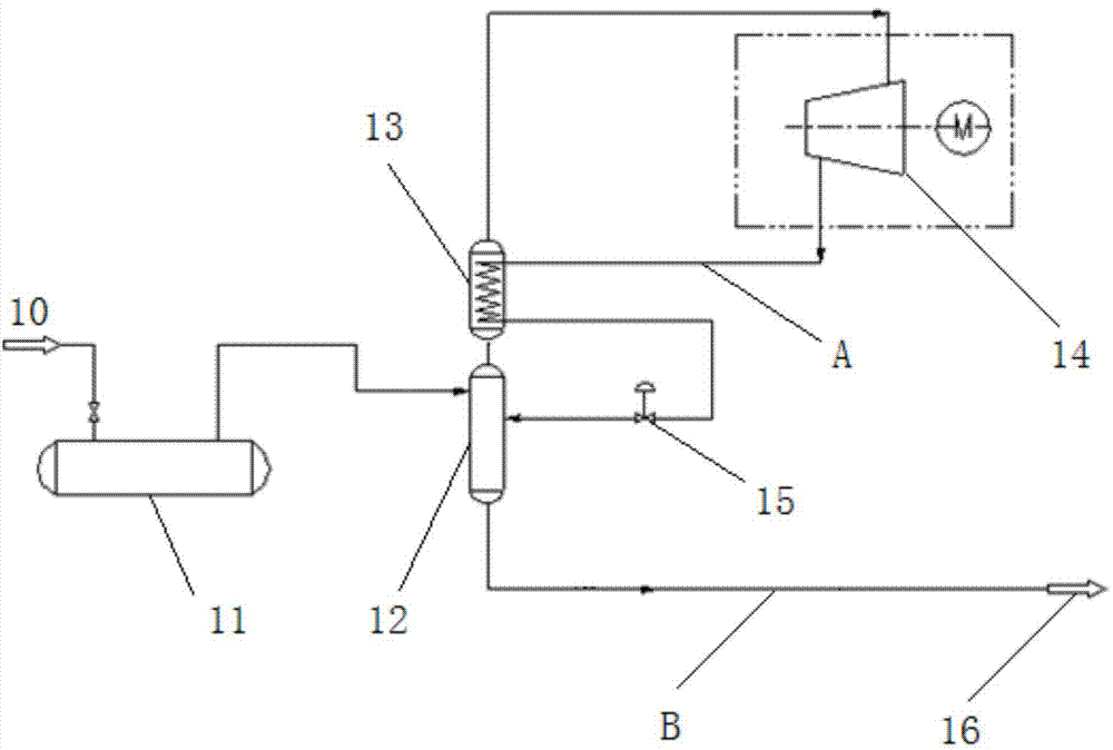
[0024] Such as figure 1 As shown, the present embodiment provides a methane gas recovery system, the system includes a flash evaporator 12, the inlet of the flash evaporator 12 is used to receive methane gas 10, the gas outlet of the flash evaporator 12 is connected to the compressor The air inlet of the compressor 14 is connected, and the air outlet of the compressor 14 is connected with the cooling device, and the cooling device is connected to the return port of the flash evaporator 12 through the throttling valve 15 .
[0025] The above is the core technical solution of the present invention. The methane gas recovery system of the present invention includes a flash evaporator 12 for receiving methane gas 10, wherein the air inlet of the flash evaporator 12 is used for receiving methane gas 10, After the methane gas enters the flash evaporator 12, it is separated into low-temperature and low-pressure methane gas and methane liquid; the gas outlet of the flash evaporator 12 ...
Embodiment 2
[0030] Such as figure 1 As shown, embodiment two is an improvement made on the basis of embodiment one. In order to improve the system for recovering methane gas, the system of embodiment one has increased recycling equipment, which will be described in detail below:
[0031]In this embodiment, the cooling device is a heat exchanger 13, and the heat exchanger 13 includes at least two channels, one of which communicates with the pipeline between the flasher 12 and the compressor 14, and the other A channel communicates with the pipeline between the compressor 14 and the throttle valve 15, and the low-temperature methane gas continuously discharged from the gas outlet of the flash evaporator 12 exchanges heat with the pressurized high-temperature methane gas, which is beneficial to Reduce energy loss.
[0032] The air inlet of the flash evaporator 12 is connected with the buffer tank 11 through a pipeline, and the flash evaporator 12 receives the methane gas 10 through the buff...
Embodiment 3
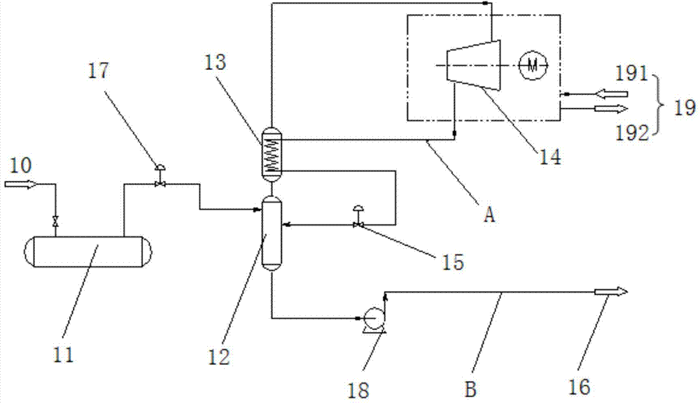
[0036] Such as figure 2 As shown, embodiment three is a deformation made on the basis of embodiment two. In order to improve the system for recovering methane gas, the system of embodiment two has increased recycling equipment, which will be described in detail below:
[0037] A valve can be set between the buffer tank 11 and the flash evaporator 12, and the valve is preferably a pressure reducing valve 17, so that the methane gas can be further reduced in temperature after decompression, and high-quality cold methane gas can be provided to the The flash evaporator 12 is conducive to the separation of methane gas in the flash evaporator 12, and the low-temperature and low-pressure methane gas in the buffer tank 11 is decompressed to 0.1MPa through the pressure reducing valve 17 and enters the flash evaporator 12. It is beneficial to obtain more methane liquid when the flasher 12 performs gas-liquid separation.
[0038] A booster pump 18 is provided between the flasher 12 and...
PUM
 Abstract
Description
Claims
Application Information