Touch panel

A touch panel and substrate technology, applied in the direction of instruments, electrical digital data processing, input/output process of data processing, etc., to achieve the effect of avoiding the increase of capacitance value and good touch sensing ability

Inactive Publication Date: 2015-06-17
WINTEK CORP
View PDF4 Cites 2 Cited by
  • Summary
  • Abstract
  • Description
  • Claims
  • Application Information

AI Technical Summary

Problems solved by technology

However, whether it is the former single-layer electrode or the latter double-layer electrode structure, there is still room for improvement in its ability to sense touch.

Method used


Image

  • Touch panel
  • Touch panel
  • Touch panel

Examples


Embodiment Construction

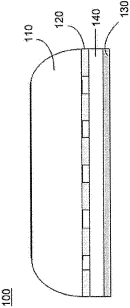
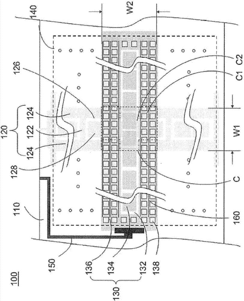
[0057] figure 1 , 2 They are respectively a schematic cross-sectional view and a schematic view of electrodes of a touch panel according to the first embodiment of the present invention. see figure 1 , figure 2 The touch panel 100 of this embodiment includes a substrate 110 , a plurality of first electrodes 120 , a plurality of second electrodes 130 and a dielectric layer 140 . For the convenience of explanation, figure 2 Only a single first electrode 120 and a second electrode 130 are shown. In this embodiment, the touch panel 100 is a capacitive touch panel; the substrate 110 is a light-transmitting cover plate, a hard substrate or a reinforced substrate with high mechanical strength, which can be made of glass or plastic material. To protect the components below it. In addition, a decoration layer may be selectively disposed on the substrate 110 , for example, disposed around the periphery of the substrate 110 , so as to shield the peripheral traces 150 along its pr...


PUM


Abstract

The invention provides a touch panel, comprising a plurality of first electrodes, a plurality of second electrodes, and a dielectric layer arranged between the first electrodes and the second electrodes, wherein the first electrodes and the second electrodes are intersected to form a plurality of interlaced areas. Each second electrode is at least provided with a plurality of open holes corresponding to each interlaced area, and the open holes expose part of the first electrodes.

Description

technical field [0001] The present invention relates to a touch panel, and in particular to a touch panel with good touch sensing capability. Background technique [0002] With the advancement of technology, plate-shaped electronic components such as touch panels and display panels have been widely used in various electronic devices, such as smart phones, GPS navigator systems, and tablet computers. (tablet PC), personal digital assistant (PDA) and notebook computer (laptop PC). [0003] Taking the touch panel as an example, in general, touch panels are divided into single-layer electrode and double-layer electrode structure; among them, the representatives of the former include self-capacitive triangular electrodes or key-type electrodes, or mutual-capacitance digital electrodes. The strip driving electrodes are matched with several receiving electrodes located between two adjacent driving electrodes. Representatives of the latter include, for example, a mutual-capacitive...

Claims


Application Information

Patent Timeline
Patent Type & Authority Applications(China)
IPC IPC(8): G06F3/044
CPCG06F3/044
Inventor 张廷宇黄湘霖苏国彰王文俊林永常王文宏陈世正林明传
Owner WINTEK CORP
Why Eureka
Try Eureka