
Row decoding circuit and memory

A decoding circuit and line decoding technology, applied in the field of circuit design, can solve problems such as difficult control and influence on the reliability of storage units

Active Publication Date: 2015-06-17
SHANGHAI HUAHONG GRACE SEMICON MFG CORP
View PDF3 Cites 2 Cited by
  • Summary
  • Abstract
  • Description
  • Claims
  • Application Information

AI Technical Summary

Problems solved by technology

However, the control gates CG1, CG2, . The rate at which the voltage drops from 0V or positive voltage to -7V negative voltage) is not easy to control, which affects the reliability of the storage unit

Method used


Image

  • Row decoding circuit and memory
  • Row decoding circuit and memory
  • Row decoding circuit and memory

Examples


Embodiment Construction

[0034] The row decoding circuit and memory of the present invention will be described in more detail below in conjunction with schematic diagrams, wherein a preferred embodiment of the present invention is shown, it should be understood that those skilled in the art can modify the present invention described here, and still realize the present invention beneficial effect. Therefore, the following description should be understood as the broad knowledge of those skilled in the art, but not as a limitation of the present invention.

[0035] In the interest of clarity, not all features of an actual implementation are described. In the following description, well-known functions and constructions are not described in detail since they would obscure the invention with unnecessary detail. It should be appreciated that in the development of any actual embodiment, numerous implementation details must be worked out to achieve the developer's specific goals, such as changing from one em...


PUM


Abstract

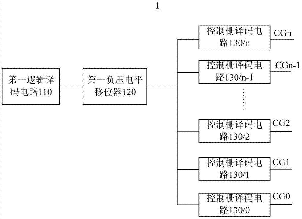
The invention reveals a row decoding circuit, which comprises n+1 control grid decoding circuits and current limiting biasing circuit; the current limiting biasing circuit comprises a first mirror image NMOS transistor and a resistive element, a source of the first mirror image NMOS transistor is input into an input voltage, a grid electrode of the first mirror image NMOS transistor is connected to a drain electrode, the drain electrode of the first mirror image NMOS transistor is connected to the resistive element in series, and the grid electrode of the first mirror image NMOS transistor outputs a bias signal; each control grid decoding circuit comprises a first NMOS transistor, a first PMOS transistor, a second NMOS transistor and a second mirror image NMOS transistor, the grid electrode of the second mirror image NMOS transistor accepts the bias signal, and a source of the second mirror image NMOS transistor is connected to the drain electrode of the first NMOS transistor. The invention also reveals a memory comprising the row decoding circuit, the row decoding circuit and the memory can provide negative pressure of controllable voltage transition rate for the control grid.

Description

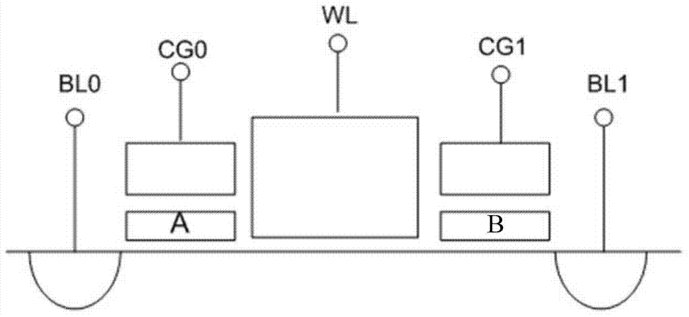
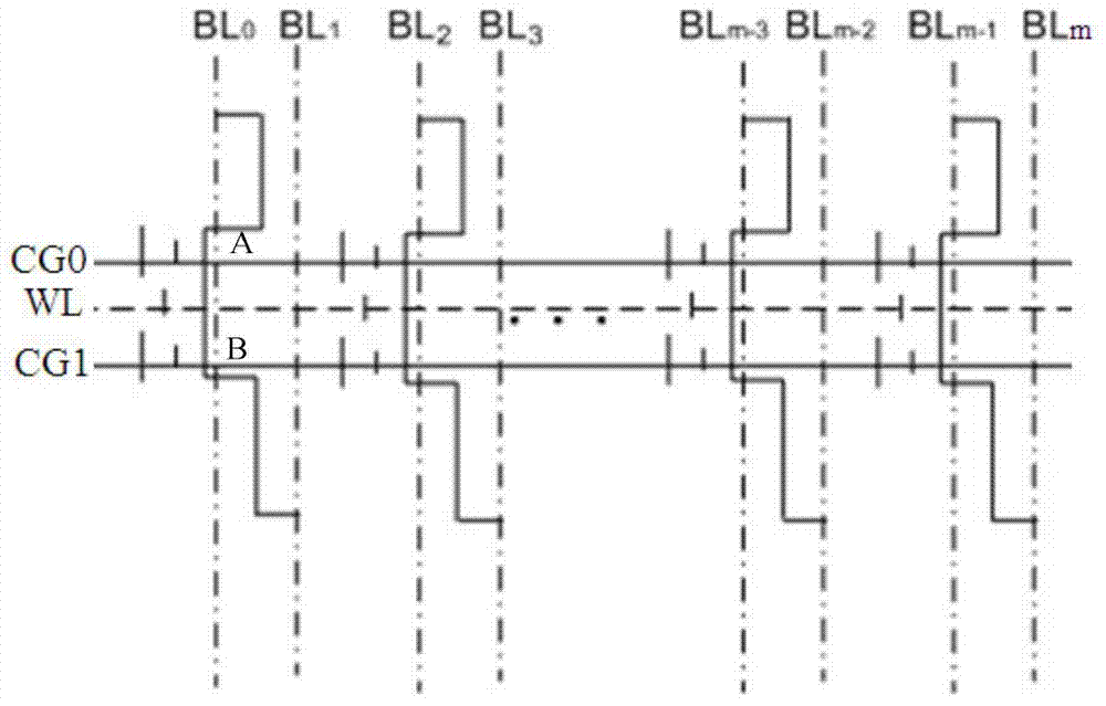
technical field [0001] The invention relates to the technical field of circuit design, in particular to a row decoding circuit and a memory. Background technique [0002] As an integrated circuit storage device, flash memory has the function of electrically erasable and writable storage of information. Therefore, flash memory is widely used in electronic products such as portable computers, mobile phones, and digital music players. Flash memory needs to arrange storage units in an array suitable for its own operation, and each storage unit is used to store a single bit of data. [0003] figure 1 is a schematic diagram of a storage unit in a flash memory in the prior art, figure 2 It is a schematic diagram of an array of storage units in a flash memory in the prior art. The flash memory includes a plurality of memory cells arranged in an array, and a plurality of bit lines (BL0, BL1, BL2, BL3, ..., BLm), word lines ( WL) and control gates (such as CG0, CG1, etc.). Such ...

Claims


Application Information

Patent Timeline
IPC IPC(8): G11C16/06
Inventor 杨光军肖军
Owner SHANGHAI HUAHONG GRACE SEMICON MFG CORP
Learn More