
LED illumination control system

A technology of LED lighting and control system, applied in the field of LED light sources, can solve the problems of high operating frequency, difficulty in heat dissipation, energy consumption of external current limiting resistors, etc., and achieve the effects of low voltage and power, high efficiency, and low cost

Inactive Publication Date: 2017-05-31
韦尚仁
View PDF0 Cites 2 Cited by
  • Summary
  • Abstract
  • Description
  • Claims
  • Application Information

AI Technical Summary

Problems solved by technology

[0002] DC LED is the mainstream of research in the packaging industry. The research direction is to improve the thermal resistance between the chip and SLUG, such as flip-chip and substrate packaging. The chip part is to improve the internal and external quantum efficiency or light extraction. Generally, the LED material As a research direction, DC LEDs have the following disadvantages: the current DC LEDs can only withstand low-voltage DC, and high-voltage or AC may damage the light-emitting diodes, so they must be used with DC conversion circuits before they can be used in commercial power systems and DC conversion systems. Generally, it consumes about 10% of the electric energy; low-voltage DC LED chips are easily damaged due to reverse voltage rise
However, the AC LED chip itself has disadvantages such as high cost, difficult insulation between grains, and difficulty in heat dissipation due to overly concentrated packaging methods; it also has stroboscopic flicker during use, energy consumption by external current-limiting resistors, and high external reactance needs to be used. The operating frequency of the LED and other issues

Method used


Image

  • LED illumination control system
  • LED illumination control system

Examples


Embodiment Construction

[0020] The working process of this structure is described in detail below in conjunction with accompanying drawing:

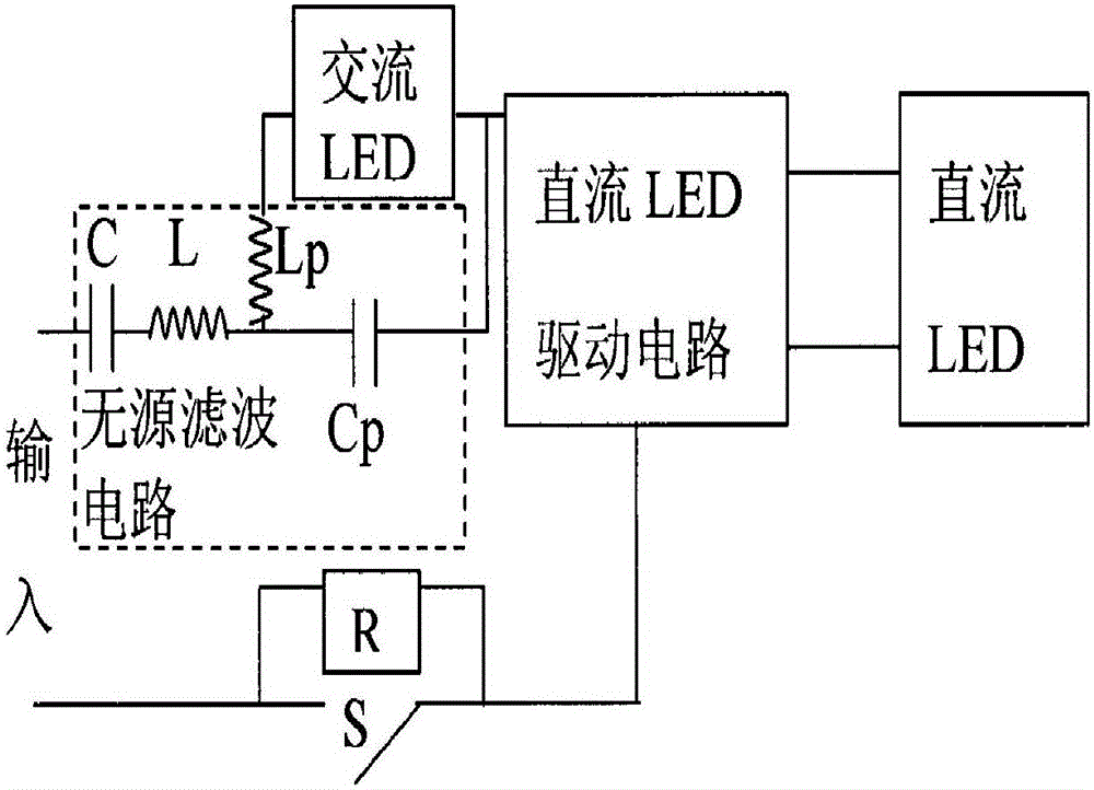
[0021] figure 1 It is a schematic diagram of the principle of an AC-DC hybrid circuit, in which the AC LED is connected in series with the AC input end of the rectifier circuit of the DC LED drive circuit (the drive circuit includes a rectifier circuit), and the DC LED drive input side is called the DC side, and the DC LED drive output side is called the DC side. On the low-voltage side, the voltage on the DC side is u1, the voltage across the LEDs connected in series on the DC side is U2, and the voltage across the LEDs connected in series on the low-voltage side is U3. Due to the small internal resistance of the LED, U2 and U3 can take the LED threshold voltage for rough control Near fixed value, set the target current as i1r, and the current control strategy is:

[0022] Step 1: Obtain i2ref from given i1r, i2ref=i1r×u1÷U3;

[0023] Step 2: Limit i2ref, ta...


PUM


Abstract

The invention discloses an LED illumination control system. A mixed type LED circuit is characterized in that a power supply side of a controllable LED circuit is serially connected with a voltage dividing LED; by controlling the output power of the controllable LED, the current flowing through the voltage dividing LED is adjusted, so the output power of the whole illumination circuit is controlled; the voltage dividing LED can be an alternating-current LED or a direct-current LED; the controllable LED can be a direct-current LED and the drive thereof or be an alternating-current LED and the drive thereof; and one part of LEDs in the LED illumination control system are free from a driving circuit, so the efficiency is quite high. Through the voltage division of the serially connected voltage dividing LED, the voltage resistance and the power of the controllable LED circuit are quite low, so the cost is lower. Thus, the system is suitable for an illumination system with quite high voltage power supply, such as commercial voltage power supply.

Description

technical field [0001] The invention belongs to the field of LED light sources, in particular to an LED lighting control system. Background technique [0002] DC LED is the mainstream of research in the packaging industry. The research direction is to improve the thermal resistance between the chip and SLUG, such as flip-chip and substrate packaging. The chip part is to improve the internal and external quantum efficiency or light extraction. Generally, the LED material As a research direction, DC LEDs have the following disadvantages: the current DC LEDs can only withstand low-voltage DC, and high-voltage or AC may damage the light-emitting diodes, so they must be used with DC conversion circuits to be used in commercial power systems and DC conversion systems. Generally, it consumes about 10% of the electric energy; low-voltage DC LED chips are easily damaged due to reverse voltage rise. [0003] For AC LEDs, the DC LED crystal grains are arranged in a matrix on a metal s...

Claims


Application Information

Patent Timeline
Patent Type & Authority Applications(China)
IPC IPC(8): H05B33/08H05B44/00
CPCH05B45/37H05B45/00Y02B20/30
Inventor 韦尚仁
Owner 韦尚仁
Learn More