DC-DC voltage converter and conversion method

A technology of DC-DC and converters, applied in the field of DC-DC voltage converters, can solve problems such as poor performance, increased design constraints, and noise generation

Active Publication Date: 2015-06-17
NXP BV
View PDF4 Cites 2 Cited by
  • Summary
  • Abstract
  • Description
  • Claims
  • Application Information

AI Technical Summary

Problems solved by technology

[0039] This overshoot is bad for DC-DC converter operation because it generates noise (EMC and switching noise)
Therefore, the implementation of the DC-DC converter increases the design constraints, because the internal components of the DC-DC should handle the electrical overload

Method used


Image

  • DC-DC voltage converter and conversion method
  • DC-DC voltage converter and conversion method
  • DC-DC voltage converter and conversion method

Examples


Embodiment Construction

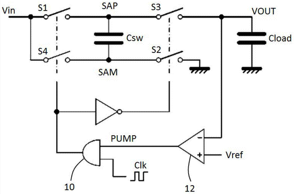
[0074] This application describes a DC-DC converter using a switched capacitor arrangement. A filter capacitor is connected between one terminal of the capacitor means and the fixed voltage line, and the calibration means are used to set or enable selection of the capacitor of the filter capacitor.

[0075] In this way, capacitors are added to the terminals of the switched capacitor arrangement. Capacitor values ​​can be selected or adjusted to keep the current capability of the DC-DC converter within specified limits.

[0076] This adjustment or selection can be achieved in two ways:

[0077] (i) Using an external capacitor

[0078] In this case, the capacitor can be selected by the user. For the required current capability of the DC-DC converter, the DC-DC converter integrated circuit can be designed for the worst case, which usually represents the highest operating temperature. Load the DC-DC converter with the maximum load current by calibrating the setup, then adjust ...


PUM


Abstract

A DC-DC converter uses a switched capacitor arrangement. A filter capacitor is connected between one terminal of the capacitor arrangement and a fixed voltage line and a calibration arrangement is used for setting or enabling selection of the capacitance of the filter capacitor. In this way, a capacitance is added to a terminal of the switched capacitor arrangement. The capacitance value can be chosen or adjusted to keep the DC-DC converter current capability within specification limits.

Description

technical field [0001] The present application relates to a DC-DC voltage converter for generating a regulated voltage output from a voltage input having a variable input voltage. The output voltage can have a higher or lower value than the input voltage, and the output voltage is stable even though the input voltage and output load may vary. Background technique [0002] Switched capacitor DC-DC voltage converters typically use "flying capacitors". These capacitors are charged from the input voltage and then discharged to the load, providing charge transfer and a constant output voltage. [0003] figure 1 A known basic DC-DC converter circuit is shown. [0004] The circuit includes a switched capacitor Csw. One terminal SAP of the switched capacitor Csw is connected to the input through a first switch S1 and to the output through a third switch S3. The other terminal SAM of the switched capacitor Csw is connected to the input through the fourth switch S4 and to ground ...

Claims


Application Information

Patent Timeline
Patent Type & Authority Applications(China)
IPC IPC(8): H02M1/32H02M1/14
CPCH02M1/14H02M1/32H02M3/07H02M1/44H02M3/158H02M1/088H04B1/40
Inventor 美拉尼·菲利普
Owner NXP BV
Why Eureka
Try Eureka