Dead Zone Compensation Method of Inverter

A technology of dead zone compensation and frequency converter, which is applied in the field of electric transmission, can solve the problems of error, compensation does not have instantaneousness and compensation value, etc., and achieve the effects of timely and accurate compensation, improving voltage utilization rate and reducing output harmonic content

Active Publication Date: 2017-04-12
ZHEJIANG CHINT ELECTRIC CO LTD
View PDF5 Cites 0 Cited by
  • Summary
  • Abstract
  • Description
  • Claims
  • Application Information

AI Technical Summary

Problems solved by technology

[0007] Among the above-mentioned several compensation methods, the compensation of equal storage is not instantaneous and the compensation value is based on the average value, so there is a defect of error

Method used


Image

  • Dead Zone Compensation Method of Inverter
  • Dead Zone Compensation Method of Inverter
  • Dead Zone Compensation Method of Inverter

Examples


Embodiment Construction

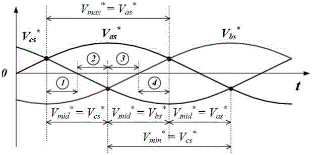
[0031] The basic principle of compensating the dead time is based on the polarity of the current and the deviation of the voltage. In traditional technology, the voltage deviation is calculated based on the average value of the voltage. The deviation voltage is averaged into the entire cycle, and then added to the vector to generate a control voltage for compensation. Generally, it needs to be converted into a compensation voltage in the dq coordinate system. Such an operation requires a large amount of calculation and the algorithm is complex, resulting in a slow response speed and unable to achieve real-time compensation.

[0032] This method proposes a method for directly compensating the output voltage deviation based on the maximum value-middle value-minimum value of the voltage, and according to the maximum value-middle value-minimum value of the voltage and the polarity of the phase current. This method analyzes the interval error of the actual switching voltage accordi...


PUM


Abstract

The present invention aims to propose a dead zone compensation method for frequency converters, which includes the following steps: the switch switching time setting step is set in one sampling period according to the on or off state of the switch tube in the three-phase inverter circuit Several switch switching times, the several switch switching times are combined with the switching delay and the dead zone delay of the switching tube. The step of obtaining the voltage map is to obtain the voltage map according to the switching time of the switch, the voltage of the DC bus, and the voltage drop of the switch tube and the diode in the three-phase inverter circuit. In the voltage map, the voltage is a constant value at each switching time of the switch. In the voltage calculation step, the maximum value, the middle value and the minimum value of the voltage are calculated according to the switching time of the switch and the fixed value of the voltage during the switching time of the switch. In the switch switching time calculation step, the actual time of each switch switching time is determined in the actual sampling period according to the voltage map, the maximum value, the middle value and the minimum value. The invention can make the compensation more timely and accurate.

Description

technical field [0001] The present invention relates to electric transmission technology, more specifically, relates to the control technology of frequency converter. Background technique [0002] The frequency converter is a key component in the electric transmission technology, and the frequency converter has dead time in the actual use process. The existence of the dead time not only reduces the output voltage, distorts the current waveform, and pulsates the motor torque, but more seriously, it will cause the motor to oscillate. How to effectively compensate the dead zone effect has become a key issue that must be solved in high-performance drive systems. [0003] The basic method of existing dead zone compensation is mainly voltage feedback or current feedback, and there is often a time lag. The voltage deviation caused by the compensation dead zone time is not instantaneous, and the compensation value is calculated after the average value. error, poor real-time perfor...

Claims


Application Information

Patent Timeline
Patent Type & Authority Patents(China)
IPC IPC(8): H02M7/5387
CPCH02M1/12H02M7/53871H02M7/53875H02M7/53876
Inventor 李长乐李兵张俊史振兴张美娟
Owner ZHEJIANG CHINT ELECTRIC CO LTD
Why Eureka
Try Eureka