Water-permeable ground system and pavement method

A ground system and permeable technology, applied in the direction of pavement details, roads, road repair, etc., can solve problems such as poor water permeability

Active Publication Date: 2015-06-24
吕国兵
View PDF9 Cites 13 Cited by
  • Summary
  • Abstract
  • Description
  • Claims
  • Application Information

AI Technical Summary

Problems solved by technology

[0004] The purpose of the present invention is to provide a permeable floor system and paving method to solve the technical problem of the permeable bricks existing in the prior art that the water permeability becomes poor after a period of use

Method used


Image

  • Water-permeable ground system and pavement method
  • Water-permeable ground system and pavement method
  • Water-permeable ground system and pavement method

Examples


Embodiment 1

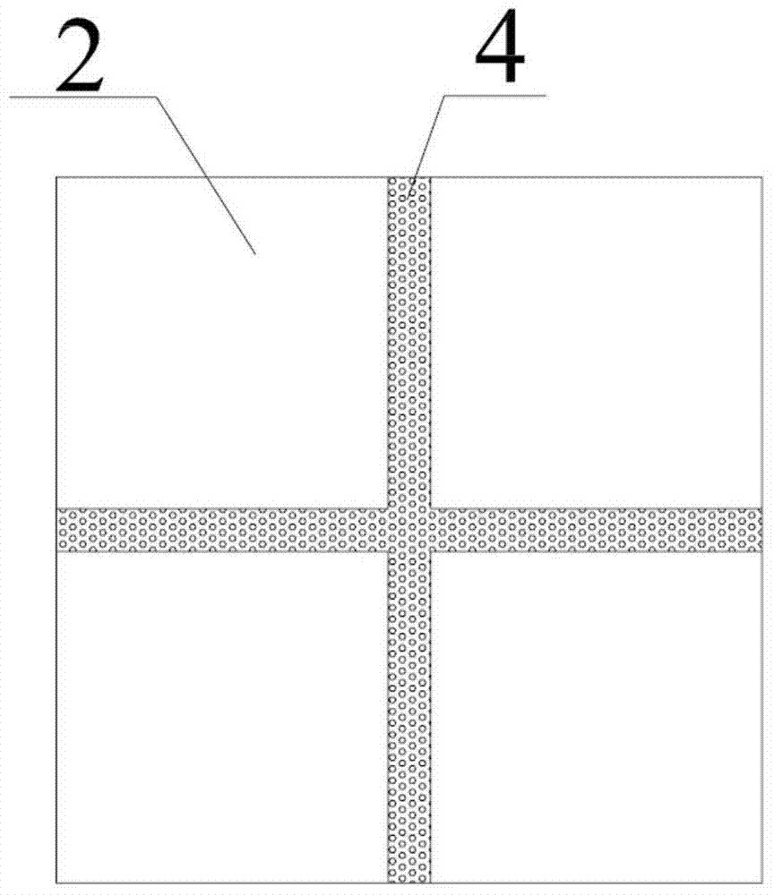
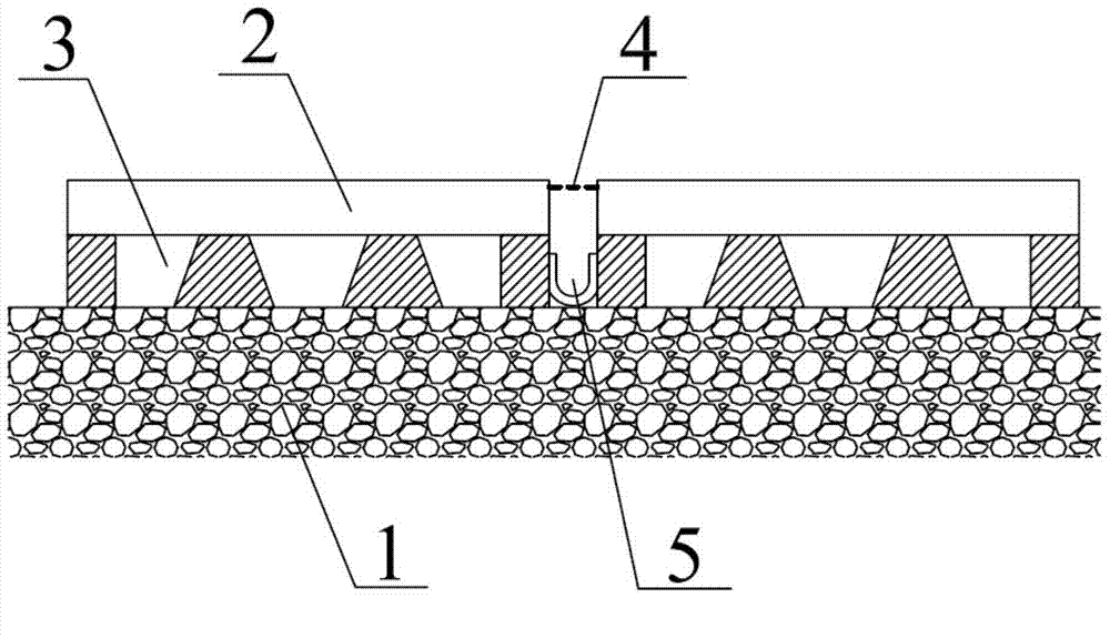
[0044] figure 1 A top view of a water-permeable ground system provided by an embodiment of the present invention; figure 2 A cross-sectional view of a water-permeable ground system provided by an embodiment of the present invention; image 3 A cross-sectional view of a water-permeable ground system provided by an embodiment of the present invention; Figure 4 A block flow diagram of a pavement method for a permeable ground provided in an embodiment of the present invention; Figure 1-4 As shown, a water-permeable ground system provided in this embodiment includes a water-permeable base layer 1, and a plurality of decorative modules are arranged on the water-permeable base layer 1;

[0045] The decorative module includes a decorative surface layer 2, the bottom of the decorative surface layer 2 is provided with a support layer 3, the support layer 3 is connected to the permeable base layer 1, and gaps are provided between adjacent decorative modules, and a permeable module i...

Embodiment 2

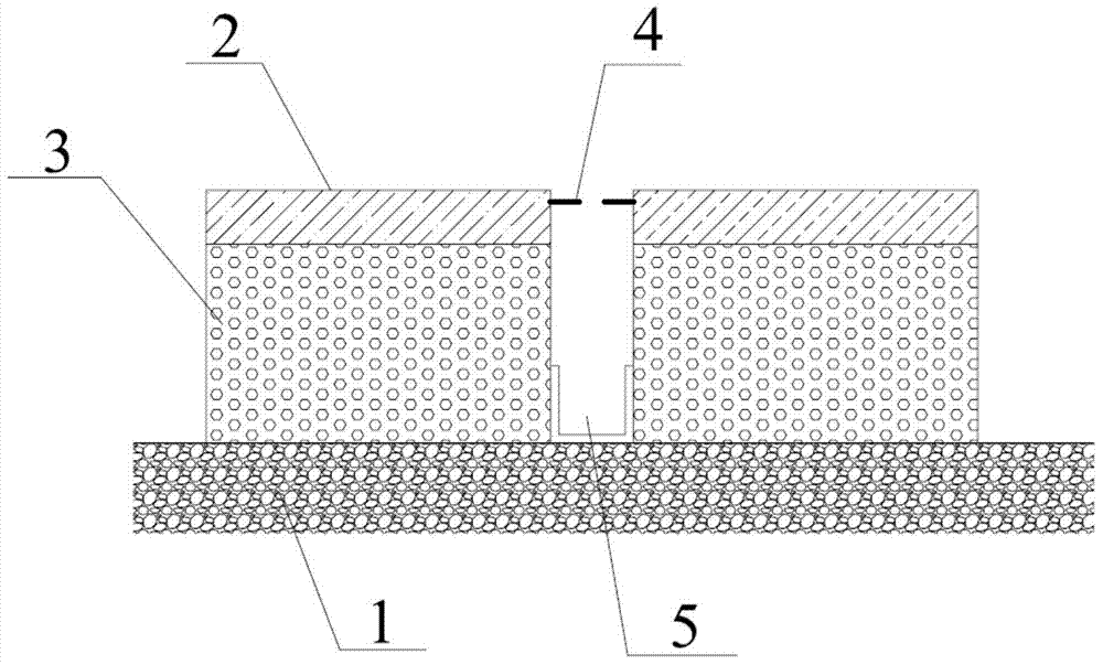
[0050] figure 1 A top view of a water-permeable ground system provided by an embodiment of the present invention; figure 2 A cross-sectional view of a water-permeable ground system provided by an embodiment of the present invention; image 3 A cross-sectional view of a water-permeable ground system provided by an embodiment of the present invention; Figure 4 A block flow diagram of a pavement method for a permeable ground provided in an embodiment of the present invention; Figure 1-4 As shown, a water-permeable ground system provided in this embodiment includes a water-permeable base layer 1, and a plurality of decorative modules are arranged on the water-permeable base layer 1;

[0051] The decorative module includes a decorative surface layer 2, the bottom of the decorative surface layer 2 is provided with a support layer 3, the support layer 3 is connected to the permeable base layer 1, and gaps are provided between adjacent decorative modules, and a permeable module i...


PUM


Abstract

The invention provides a water-permeable ground system which comprises a water-permeable base layer. Multiple decoration modules are arranged on the water-permeable base layer; each decoration module comprises a decorative surface layer, the bottom of each decorative surface layer is provided with a support layer, a gap is arranged between each two adjacent decoration modules, a water-permeable module is arranged in each gap and comprises a water-permeable strip, each water-permeable strip comprises multiple water-permeable holes, and the water-permeable holes are through non-bent holes. According to the water-permeable ground system provided by the invention, water is infiltrated downwards through the water-permeable holes, and the water-permeable holes are just formed in the water-permeable strips, so that the stroke is short; the water-permeable holes are straight holes, so that a jamming phenomenon is unlikely to occur; impurities can be precipitated and stored in the gaps; if the water-permeable holes are jammed, the problem can be solved just by sweeping or cleaning by using water; impurities in the gaps are regularly cleaned or the water-permeable strips are regularly replaced, so that a jamming phenomenon caused by impurity accumulation after the system is used for a long time can be avoided. The water-permeable ground system has the characteristics of long service life and smooth water permeation.

Description

technical field [0001] The invention relates to the technical field of road paving, in particular to a permeable ground system and a paving method. Background technique [0002] With the development of urban construction, the area of ​​non-permeable floor decoration is increasing, the environment is seriously affected, and the urban heat island effect, flood disasters, groundwater depletion and other phenomena are becoming more and more serious. Therefore, it is imminent to increase urban permeable ground, and products such as permeable bricks and permeable concrete have emerged as the times require. [0003] However, due to the serious pollution of the urban environment and the large amount of dust and other particles, the newly laid permeable bricks and permeable concrete floors have an ideal water permeable effect. Permeable bricks and permeable concrete are about 6cm thick and have long holes. After a period of time, it is very easy to cause the accumulation of debris,...

Claims


Application Information

Patent Timeline
Patent Type & Authority Applications(China)
IPC IPC(8): E01C11/24
CPCE01C11/225E01C2201/20
Inventor 吕国兵吕逸凡
Owner 吕国兵
Why Eureka
Try Eureka