Vertical multi-stage centrifugal pump and constant-pressure water supply unit

A centrifugal pump and vertical technology, applied in the field of centrifugal pumps, can solve problems such as construction space limitation, damage to electrical equipment, paralysis of water supply system, etc., to avoid leakage and facilitate installation and operation.

Inactive Publication Date: 2015-06-24
山东洪涨泵业有限公司
View PDF9 Cites 5 Cited by
  • Summary
  • Abstract
  • Description
  • Claims
  • Application Information

AI Technical Summary

Problems solved by technology

[0002] As a new type of water supply equipment, constant pressure water supply units are mostly used in newly built, expanded and renovated residential buildings, residential quarters, office buildings and other places. In order to save space and land, their storage locations are mostly placed in underground pump rooms. Once a water accident occurs, the unit will be damaged if it is submerged and soaked in water, causing the entire water supply system to be paralyzed, thereby affecting people's normal living water
[0003] Vertical multistage centrifugal pump is the main tool for various operations such as water supply, industrial pressurization, industrial liquid transportation, water treatment, irrigation, etc., because of its own structure and the key components of the pump motor cannot be in contact with water. The manufacture and use of the
When encountering problems such as flooding, mechanical seal damage, and water running out of the pump room, it is easy to cause water to enter the motor or be damp to cause damage to the motor equipment, and the water inlet and outlet of the vertical multistage centrifugal pump are usually in a straight line, which affects the construction space. There are certain restrictions, while the efficiency of the installation operation is low

Method used


Image

  • Vertical multi-stage centrifugal pump and constant-pressure water supply unit
  • Vertical multi-stage centrifugal pump and constant-pressure water supply unit

Examples


Embodiment Construction

[0013] The principles and features of the present invention are described below in conjunction with the accompanying drawings, and the examples given are only used to explain the present invention, and are not intended to limit the scope of the present invention.

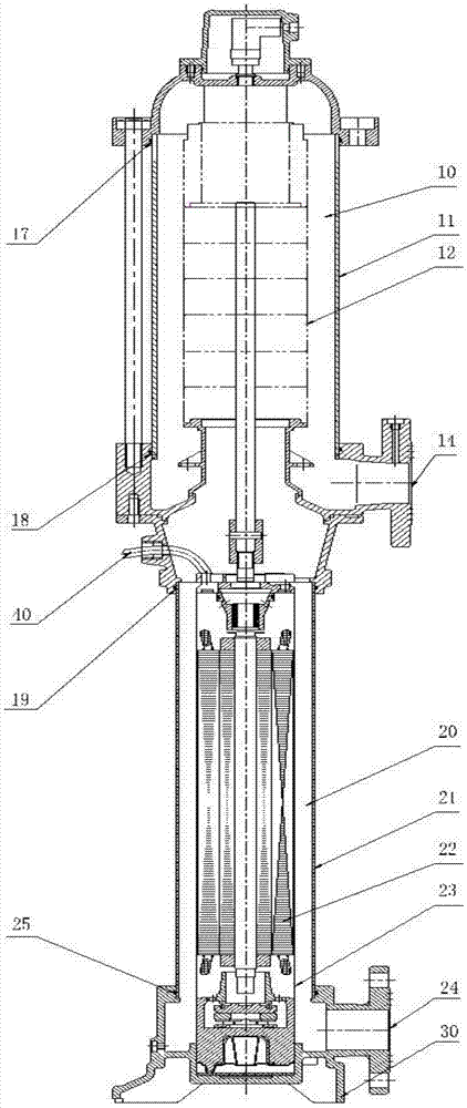
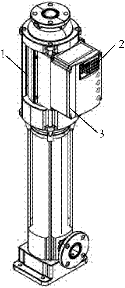
[0014] like figure 1 As shown, a constant pressure water supply unit includes a vertical multistage centrifugal pump 1 and a frequency converter 2, the frequency converter 2 is provided with a cast aluminum sealing shell 3, and the frequency converter 2 is completely sealed with the vertical multistage centrifugal pump 1 The radiator of the outer wall is fixedly connected. The frequency converter 2 generates heat during operation, and the water circulating in the vertical multistage centrifugal pump 1 can dissipate heat from the frequency converter 2 . like figure 2 As shown, a vertical multistage centrifugal pump 1 includes a pump body 12, a motor 22, a cable 40 and a base 30, the pump body 12 and the motor 22 a...


PUM


Abstract

The invention relates to a vertical multi-stage centrifugal pump which comprises a pump body, a motor, a cable and a base. The pump body and the motor are arranged on the base, the centrifugal pump further comprises a pump bowl, and the interior of the pump bowl is divided into an upper cavity and a lower cavity, wherein the upper cavity and the lower cavity are arranged up and down and communicated with each other. The pump body is arranged in the upper cavity, the motor is arranged in the lower cavity in a sealed mode, a water inlet is horizontally formed in the lower end of the lower cavity in the radial direction, the water outlet is communicated with the upper cavity through a fastening bolt, and the water outlet can be located in the lower end of the upper cavity in multiple horizontal directions. The centrifugal pump can avoid leakage caused by mechanical seal abrasion, water flowing in the centrifugal pump can cool the motor, the direction of the water outlet can be adjusted, and installation is convenient and quick. The invention further relates to a constant-pressure water supply unit which comprises a frequency converter and the vertical multi-stage centrifugal pump, the frequency converter is connected with the vertical multi-stage centrifugal pump in a sealed mode, and water flowing in the centrifugal pump can also cool the frequency converter.

Description

technical field [0001] The invention belongs to a centrifugal pump, in particular to a vertical multistage centrifugal pump powered by a water-cooled motor or a shielded motor and the pump body has no mechanical seal. The invention also relates to a constant-pressure water supply unit. Background technique [0002] As a new type of water supply equipment, constant pressure water supply units are mostly used in newly built, expanded and renovated residential buildings, residential quarters, office buildings and other places. In order to save space and land, their storage locations are mostly placed in underground pump rooms. Once a water run accident occurs, the unit will be damaged if it is submerged and soaked in water, causing the entire water supply system to be paralyzed, thereby affecting people's normal domestic water use. [0003] Vertical multistage centrifugal pump is the main tool for various operations such as water supply, industrial pressurization, industrial li...

Claims


Application Information

Patent Timeline
Patent Type & Authority Applications(China)
IPC IPC(8): F04D1/06F04D13/06F04D29/44F04D29/08F04D29/58E03B11/16
CPCF04D1/06F04D13/06F04D29/086F04D29/445F04D29/586F04D29/5806
Inventor 崔洪章宋秋谭立华
Owner 山东洪涨泵业有限公司
Why Eureka
Try Eureka