Diffuser, centrifugal compression type power system and bladeless fan

A power system and centrifugal compression technology, which is applied in the direction of machines/engines, non-variable pumps, liquid fuel engines, etc., can solve problems such as inconvenient installation and disassembly, complex structure, increased assembly strength and production costs

Active Publication Date: 2015-06-24
GD MIDEA ENVIRONMENT APPLIANCES MFG +1
View PDF5 Cites 9 Cited by
  • Summary
  • Abstract
  • Description
  • Claims
  • Application Information

AI Technical Summary

Problems solved by technology

However, such a complex structure is not convenient for installation and disassembly, which increases assembly strength and production costs.

Method used


Image

  • Diffuser, centrifugal compression type power system and bladeless fan
  • Diffuser, centrifugal compression type power system and bladeless fan
  • Diffuser, centrifugal compression type power system and bladeless fan

Examples


Embodiment Construction

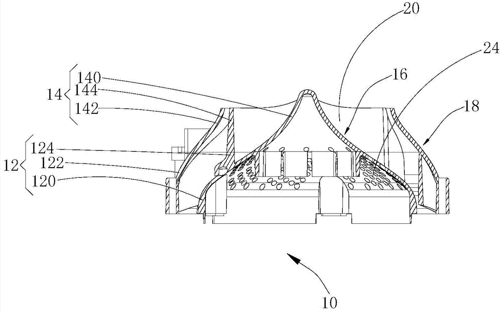
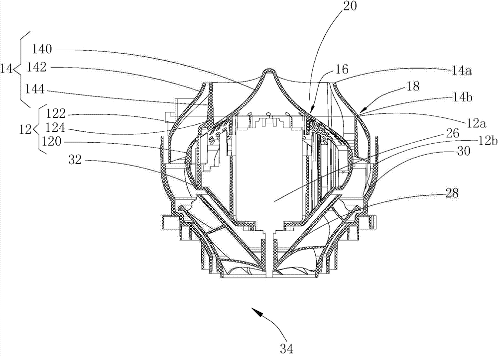
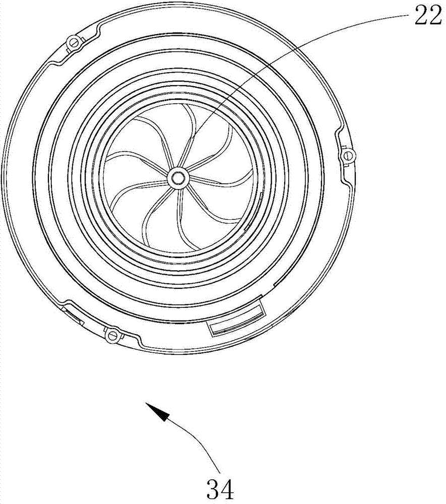
[0019] Embodiments of the present invention are described in detail below, examples of which are shown in the drawings, wherein the same or similar reference numerals denote the same or similar elements or elements having the same or similar functions throughout. The embodiments described below by referring to the figures are exemplary only for explaining the present invention and should not be construed as limiting the present invention.

[0020] In describing the present invention, it should be understood that the terms "center", "longitudinal", "transverse", "length", "width", "thickness", "upper", "lower", "front", " Orientation indicated by rear, left, right, vertical, horizontal, top, bottom, inside, outside, clockwise, counterclockwise, etc. The positional relationship is based on the orientation or positional relationship shown in the drawings, which is only for the convenience of describing the present invention and simplifying the description, rather than indicating ...


PUM


Abstract

The invention discloses a diffuser. The diffuser comprises a lower-portion component and an upper-portion component. The upper-portion component is fixed to the lower-portion component, and the upper-portion component and the lower-portion component are formed respectively. The lower-portion component comprises a lower-portion inner wall and a lower-portion outer wall, the upper-portion component comprises an upper-portion inner wall and an upper-portion outer wall, the upper-portion inner wall and the lower-portion inner wall are connected to form an inner air guide surface, the upper-portion outer wall and the lower-portion outer wall are connected to form an outer air guide surface, and the inner air guide surface and the outer air guide surface oppositely define an air guide channel used for diffusing airflow. The upper-portion component further comprises an upper air guide fin connected with the upper-portion inner wall and the upper-portion outer wall, the lower-portion component further comprises a lower air guide fin connected with the lower-portion inner wall and the lower-portion outer wall, and the upper air guide fin and the lower air guide fin are connected to form an air guide fin connected with the inner air guide surface and the outer air guide surface. In this way, breakage, caused by contraction deformation, of the air guide fin is reduced. The diffuser is simple in structure and convenient to assemble and disassemble. The invention further discloses a centrifugal compression type power system and a bladeless fan.

Description

technical field [0001] The invention relates to centrifugal compression technology, in particular to a diffuser, a centrifugal compression power system and a bladeless fan. Background technique [0002] Existing bladeless fans generally include diffusers. The air guide fins of the diffuser are arranged between the outer wall and the inner wall, but the shrinkage and deformation of the air guide fins are likely to cause breakage. Therefore, the air guide vanes of diffusers in the prior art are mostly formed separately and then fixed between the inner wall and the outer wall; . However, such a complex structure is not convenient for installation and disassembly, which increases assembly strength and production cost. Contents of the invention [0003] The present invention aims to solve at least one of the technical problems existing in the prior art. Therefore, the present invention needs to provide a diffuser. [0004] The present invention also needs to provide a cent...

Claims


Application Information

Patent Timeline
Patent Type & Authority Applications(China)
IPC IPC(8): F04D29/44F04D25/08
CPCF04D25/08F04D29/441
Inventor 豆海邵琛马列李殿飞靳思宇滕国华张辉
Owner GD MIDEA ENVIRONMENT APPLIANCES MFG
Why Eureka
Try Eureka