
Heating pipe of instant heating faucet

A heating tube and faucet technology, applied in valve heating/cooling devices, water heaters, fluid heaters, etc., can solve problems such as increasing the contact time between water flow and heating tubes, poor heating effect, and increasing the volume of electrical appliances. Achieve the effect of shortening heating time, accelerating heating rate and saving water resources

Active Publication Date: 2015-06-24
慈溪万陇电器有限公司
View PDF11 Cites 6 Cited by
  • Summary
  • Abstract
  • Description
  • Claims
  • Application Information

AI Technical Summary

Problems solved by technology

[0008] Both of the above two patents change the flow path of the water flow, making the flow path from the liquid inlet to the liquid outlet more tortuous and longer, increasing the contact time between the water flow and the heating pipe, although effectively improving the heating efficiency of the water body. speed, but when the faucet is just turned on, more cold water needs to be drained or it takes a long time to wait for hot water, which not only wastes water resources, but also cannot achieve the effect of quickly dispensing hot water as soon as the faucet is turned on
There are other products that increase the heating speed by increasing the number of heat pipes, but the disadvantage is that it not only increases the size of the electrical appliance, but also increases the cost
In addition, due to the poor heating effect, the hot water from the tap may be mixed with some bacteria, which is harmful to human health

Method used


Image

  • Heating pipe of instant heating faucet
  • Heating pipe of instant heating faucet
  • Heating pipe of instant heating faucet

Examples


Embodiment 1

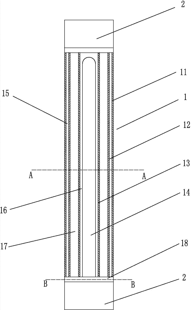
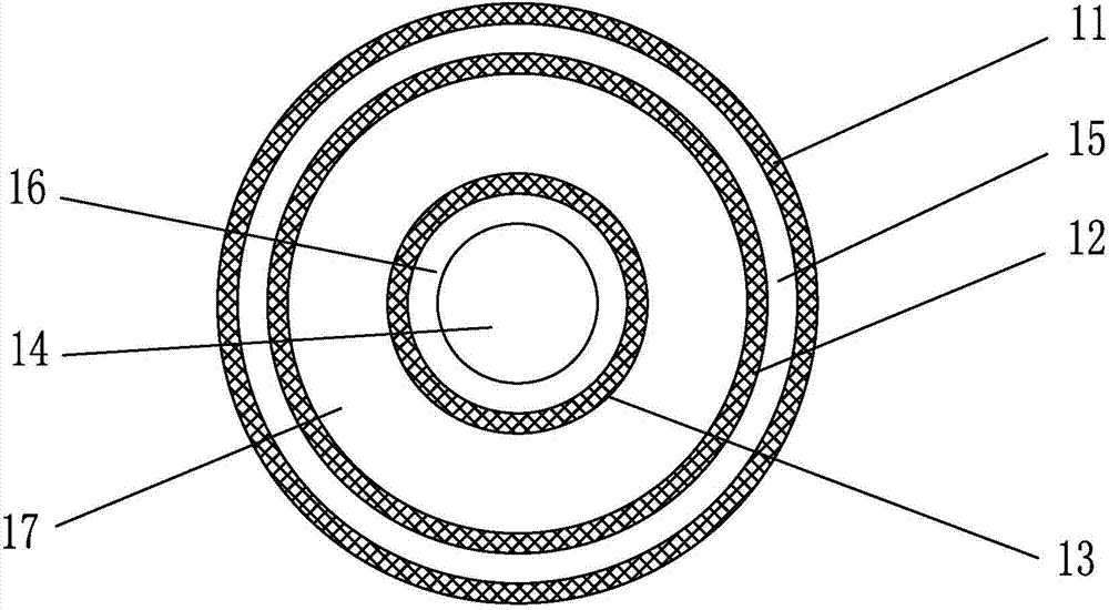
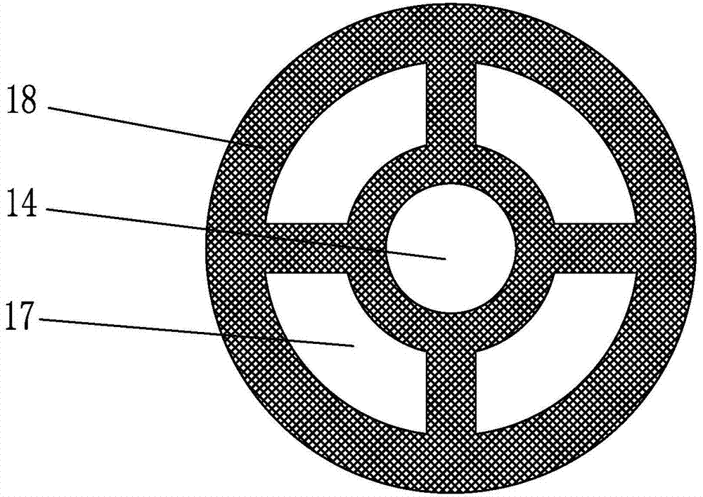
[0027] Such as Figure 4 As shown, a heat pipe of an instant water faucet includes three heat pipe bodies 1 connected in series with water inlets and water outlets at both ends, electrodes 2 arranged at both ends of the heat pipe body, and electrodes 2 for fixing the heat pipe. Fixing seats 3 at the two ends of the body. Such as figure 1 , 2 As shown in , 3, the heating pipe body includes an insulating shell 11, a first heating tube 12, and a second heating tube 13 whose diameters are successively reduced, and the insulating shell, the first heating tube and the second heating tube are coaxial, and The first heating cylinder is arranged in the insulating casing, the second heating cylinder is arranged in the first heating cylinder, the first heat insulation layer 15 is closed between the insulating casing and the first heating cylinder, the first heating cylinder and the second heating tube The intermediate water body flow channel 17, the outer wall of the first heating tub...

Embodiment 2

[0032] Such as Figure 4 As shown, a heat pipe of an instant water faucet includes three heat pipe bodies 1 connected in series with water inlets and water outlets at both ends, electrodes 2 arranged at both ends of the heat pipe body, and electrodes 2 for fixing the heat pipe. Fixing seats 3 at the two ends of the body. Such as figure 1 , 2 As shown in , 3, the heating pipe body includes an insulating shell 11, a first heating tube 12, and a second heating tube 13 whose diameters are successively reduced, and the insulating shell, the first heating tube and the second heating tube are coaxial, and The first heating cylinder is arranged in the insulating casing, the second heating cylinder is arranged in the first heating cylinder, the first heat insulation layer 15 is closed between the insulating casing and the first heating cylinder, the first heating cylinder and the second heating tube The intermediate water body flow channel 17, the outer wall of the first heating tub...


PUM


Abstract

The invention relates to the field of structural design of electric water heater heating pipes, and discloses a heating pipe of an instant heating faucet. The heating pipe comprises a heating pipe body, electrodes and a fixing seat which are coaxial. The heating pipe body comprises an insulating shell, a first heating barrel and a second heating barrel, the first heating barrel is arranged in the insulating shell, the second heating barrel is arranged in the first heating barrel, a first heat preservation layer is arranged between the insulating shell and the first heating barrel, a water passageway is arranged between the first heating barrel and the second heating barrel, the outer wall of the first heating barrel and the inner wall of the second heating barrel are coated with resistive films, an ultraviolet lamp tube coaxial with the second heating barrel is arranged in the second heating barrel, a second heat preservation layer is arranged between the ultraviolet lamp tube and the second heating barrel, and sealing devices are arranged on a water inlet and a water outlet of the heating pipe body. The water heating efficiency is higher, the heating speed is higher, the length of the water passageway is not increased, and the water outflow speed is high. The sterilization function is achieved.

Description

technical field [0001] The invention relates to the field of structural design of heating pipes of electric water heaters, in particular to a heating pipe of an instant water faucet. Background technique [0002] With the development of society, instant electric water heaters are more and more used in the daily life of ordinary people, for example, small kitchen treasures, instant drinking fountains, instant faucets, etc. These instant heating The equipment brings great convenience to people and saves waiting time. [0003] However, with the gradual improvement of people's requirements, people have higher requirements for the heating speed of instant electric water heaters. In order to improve the heating efficiency, many products upgrade and optimize the structure of the heating pipes of electric water heaters. [0004] The Chinese utility model patent of CN 202234846U discloses a heat pipe of an instant water dispenser, including a heat pipe, and the inner wall of the hea...

Claims


Application Information

Patent Timeline
IPC IPC(8): F16K49/00F24H1/10F24H9/18
CPCF16K49/002F24H1/102F24H9/1863
Inventor 陈亚红
Owner 慈溪万陇电器有限公司
Learn More