
Embankment safety monitoring method based on self-adaption feedback-type vibrating wire sensor

A technology of vibrating wire sensor and vibrating wire sensor, which is applied in the direction of using electric/magnetic devices to transmit sensing components, etc., can solve the problems of short vibration duration of steel strings, accelerated aging of steel strings, and difficult signal pickup, etc., to reduce time , improve work efficiency, and ensure the effect of accuracy and reliability

Inactive Publication Date: 2015-06-24
EAST CHINA JIAOTONG UNIVERSITY
View PDF5 Cites 9 Cited by
  • Summary
  • Abstract
  • Description
  • Claims
  • Application Information

AI Technical Summary

Problems solved by technology

The limitations of these two excitation methods are as follows: high-voltage string excitation, steel string vibration duration is short, the signal is not easy to pick up, measurement accuracy is poor, and high voltage is easy to accelerate the aging of the steel string and cause the sensor to fail; Although the high-frequency excitation method uses low-voltage excitation to protect the steel strings, the frequency sweep signal is a continuous pulse signal from the lower limit of the frequency to the upper limit of the frequency. In order to ensure the excitation effect, the pulse of each frequency must last for several cycles. Excitation time is too long

Method used


Image

  • Embankment safety monitoring method based on self-adaption feedback-type vibrating wire sensor
  • Embankment safety monitoring method based on self-adaption feedback-type vibrating wire sensor

Examples


Embodiment Construction

[0022] Specific embodiments of the present invention are described in detail below, but it should be understood that the protection scope of the present invention is not limited by the specific embodiments.

[0023] Unless expressly stated otherwise, throughout the specification and claims, the term "comprise" or variations thereof such as "includes" or "includes" and the like will be understood to include the stated elements or constituents, and not Other elements or other components are not excluded.

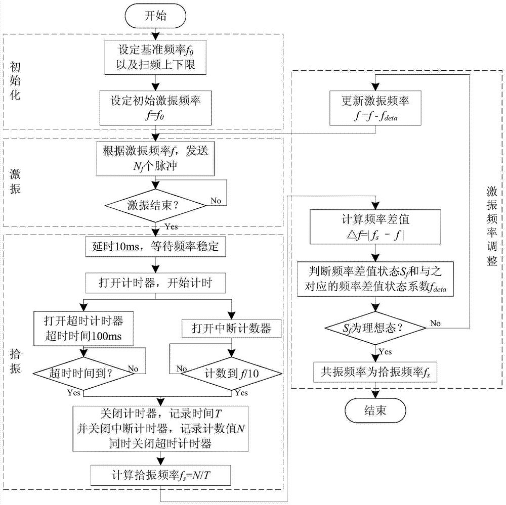
[0024] like figure 1 As shown, a dam safety monitoring method based on adaptive feedback vibrating wire sensor, the steps are:

[0025] (1) Initialize, set the reference frequency f of the initial state of the vibrating wire sensor 0 , frequency upper limit f top and the lower frequency limit f bottom . Since different vibrating wire sensors have different working principles, the changing direction of the steel string after being stressed is also different. According to t...


PUM


Abstract

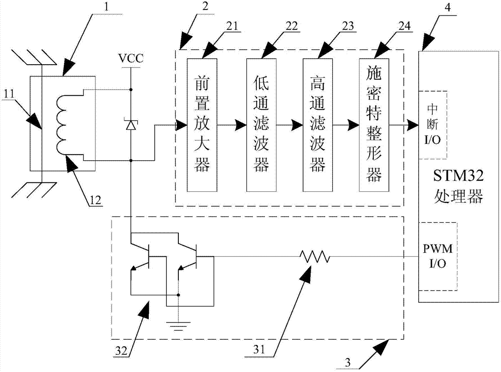
The invention discloses an embankment safety monitoring method based on a self-adaption feedback-type vibrating wire sensor. The method comprises the steps that initial resonant frequency is taken as initial exciting frequency, and the total number of pulses N<f> needed by string wire minimum vibration is adopted to achieve self-adaption adjustment of exciting time; a double trigger mode of an interrupt counter and a time-out timer of a STM32 processor is adopted to determine the end of vibration picking, vibration picking time is counted, and vibration picking frequency is calculated according to an equal-precision frequency measuring method; a concept of a frequency difference value state S<f> is introduced, a different value between the vibration picking frequency and the exciting frequency is calculated, and the state of the S<f> is determined. When the S<f> is in an ideal state, the vibration picking frequency is the resonant frequency; when the S<f> is in a non-ideal state, the exciting frequency is updated according to a formula which is shown in a specification, and excitation is conducted again. By means of the embankment safety monitoring method based on the self-adaption feedback-type vibrating wire sensor, one-time exciting time is reduced, and the safety monitoring efficiency of an embankment is improved; equal-precision self-adaption adjustment is achieved based on a feedback-type frequency sweep method, the safety monitoring time of the embankment is shortened.

Description

Technical field: [0001] The invention belongs to the field of vibrating wire sensor monitoring, in particular to a dam safety monitoring method based on an adaptive feedback type vibrating wire sensor. Background technique: [0002] The vibrating wire sensor has the characteristics of simple structure, good stability and high detection accuracy, and the output signal of the vibrating wire sensor is a frequency signal. Because the frequency signal can be transmitted over a long distance, the vibrating wire sensor can be applied to long-distance detection field. Therefore, vibrating wire sensors are widely used in engineering safety detection of dams, bridges, subways, coal mines, and foundation pits. [0003] The vibration method used for vibrating wire sensor monitoring is generally divided into two types: high-voltage plucked string excitation and low-voltage sweep frequency excitation, but these two excitation methods have relatively large limitations. The high-voltage s...

Claims


Application Information

Patent Timeline
IPC IPC(8): G01D5/12
Inventor 汤文亮文波黄德昌李瑞徐志成梁煜高新诚王一帆
Owner EAST CHINA JIAOTONG UNIVERSITY
Learn More