
Long-pupillary-distance and shortwave infrared spectral imaging objective lens

An infrared spectroscopy, imaging objective lens technology, applied in optics, optical components, instruments, etc., can solve the problems of reduced transmittance, difficult chromatic aberration correction, inability to effectively correct chromatic aberration, etc., to achieve good spectral transmittance and increase the field of view. Ability, good achromatic effect

Inactive Publication Date: 2015-06-24
XI'AN INST OF OPTICS & FINE MECHANICS - CHINESE ACAD OF SCI
View PDF5 Cites 2 Cited by
  • Summary
  • Abstract
  • Description
  • Claims
  • Application Information

AI Technical Summary

Problems solved by technology

[0011] One of the important means of correcting the chromatic aberration of the optical system is to use the different dispersion properties of the optical material to distribute the focal power reasonably. Usually, the transmissive optical system is composed of several lenses with positive and negative focal powers. When performing chromatic aberration correction in the short-wave infrared band, the crown glass with small dispersion is often used as the positive lens, and the flint glass with large dispersion is used as the negative lens. However, the dispersion characteristics of these two types of glasses change in the short-wave infrared band. Realize the correction of chromatic aberration. This method cannot effectively correct chromatic aberration. At the same time, the transmittance of crown glass also decreases between 2200nm and 2500nm, which cannot meet the performance requirements of the optical system. The infrared spectral band must be matched with suitable optical materials and a reasonable structural type to achieve chromatic aberration correction in this band

Method used


Image

  • Long-pupillary-distance and shortwave infrared spectral imaging objective lens
  • Long-pupillary-distance and shortwave infrared spectral imaging objective lens

Examples


Embodiment Construction

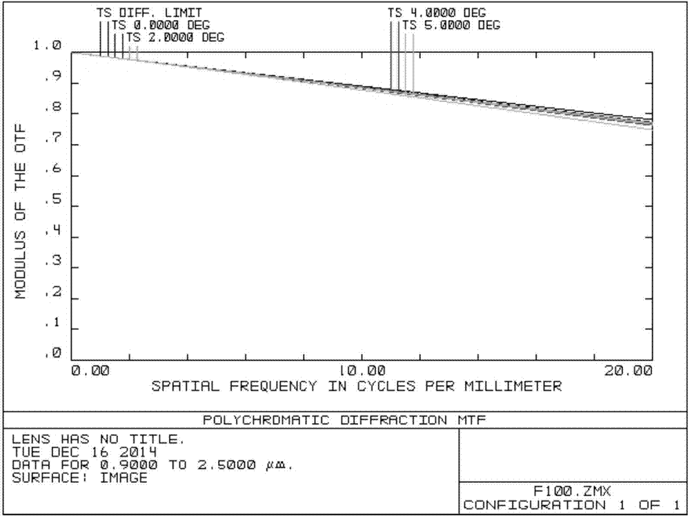
[0021] Such as figure 1 As shown, the imaging objective lens includes a diaphragm and lenses 1-5, which are sequentially arranged on the system optical axis oo' together with the image plane (imaging detector).

[0022] The diaphragm is placed in front of the system at a distance of 1.8 times the focal length from the first lens element.

[0023] Lens 1 is a biconvex lens with positive refractive power, and the material used is caf2. Lens 2 is a meniscus lens with negative refractive power that bends toward the diaphragm, and the material used is SF6. Lens 3 is a biconvex lens with positive refractive power. Lenses, the material used is caf2;

[0024] Both caf2 and Baf2 can be used for lenses with positive power, and ZF or SF series can be used for lenses with negative power, so lenses 1, 2, and 3 can be combined in three ways, namely positive-negative-positive, negative ‐Positive‐positive, positive‐positive‐negative combinations.

[0025] Lens 4 is a thick meniscus lens wi...


PUM


Abstract

The invention discloses a long-pupillary-distance and shortwave infrared spectral imaging objective lens. The objective lens comprises five optical lenses which are sequentially arranged on a system optical axis from a light bar to an image surface. An achromatism glass pair with the focal power of positive, negative and negative is formed by the first three optical lenses. A very good achromatism capability is achieved on the short wave infrared outer section through the combination of fluoride glass and dense flint glass, and meanwhile a high spectrum transmittance rate is achieved. The fourth optical lens is used for balancing astigmatism and the curvature of field of the system to increase the view field capability of the imaging objective lens. The fifth optical lens is used for further compensating for the astigmatism of the objective lens and meanwhile is used for meeting the requirement of the imaging objective lens for telecentric performance in image space. Finally, the requirement for the achromatism in the long papillary distance and shortwave infrared band can be met.

Description

Technical field: [0001] The invention relates to an optical imaging objective lens, in particular to a long-pupil distance short-wave infrared imaging objective lens for spectral imaging. Background technique: [0002] Spectral imaging is an imaging detection method that integrates images and spectra. The obtained image data is generally a data cube that contains two-dimensional spatial information and one-dimensional spectral information. [0003] There are three main types of spectral imaging technologies commonly used at present: [0004] The first type of spectral imaging technology uses optical filter technology to obtain spectral data of images; [0005] The second type of spectral imaging technology uses dispersion technology to obtain the spectral data of an image; [0006] The third category is the interference spectral imaging technology using Fourier transform spectroscopy technology. [0007] In particular, the third type of interference spectroscopy imaging t...

Claims


Application Information

Patent Timeline
Patent Type & Authority Applications(China)
IPC IPC(8): G02B13/14G02B13/22G02B1/00
CPCG02B13/14G02B1/00G02B9/60G02B13/22
Inventor 白清兰李立波邹纯博闫鹏冯玉涛石大莲费小云卫翠玉胡柄樑
Owner XI'AN INST OF OPTICS & FINE MECHANICS - CHINESE ACAD OF SCI
Learn More