Display panel and manufacturing method thereof and display device

A technology for a display panel and a manufacturing method, which is applied to the housings with display/control units, electrical equipment housings/cabinets/drawers, instruments, etc., which can solve the problems of unfavorable display panels such as narrow borders and widened spaces, and achieve width reduction. Small size, reduced gap width, and the effect of preventing light leakage

Inactive Publication Date: 2015-06-24
BOE TECH GRP CO LTD +1
View PDF4 Cites 11 Cited by
  • Summary
  • Abstract
  • Description
  • Claims
  • Application Information

AI Technical Summary

Problems solved by technology

However, the display panel with the above structure is provided with a black matrix 4 in the frame area to prevent light leakage from the display panel, so in the design, in order to use ultraviolet light to cure the frame sealant 5 from the side of the array substrate 1, ensure that There is enough light to pass through so that the sealant 5 is completely cured, and a wide gap needs to be set in the area where the GOA drive circuit 3 is located and between the peripheral traces, so that the GOA drive circuit 3 and the peripheral traces as a whole The occupied space becomes wider, which is not conducive to realizing the narrow border of the display panel

Method used


Image

  • Display panel and manufacturing method thereof and display device
  • Display panel and manufacturing method thereof and display device
  • Display panel and manufacturing method thereof and display device

Examples


Embodiment Construction

[0031] The specific implementation manners of the display panel provided by the embodiments of the present invention, its manufacturing method and the display device will be described in detail below with reference to the accompanying drawings.

[0032] The shapes and sizes of the regions in the drawings do not reflect the true proportions of the display panel, but are only intended to schematically illustrate the content of the present invention.

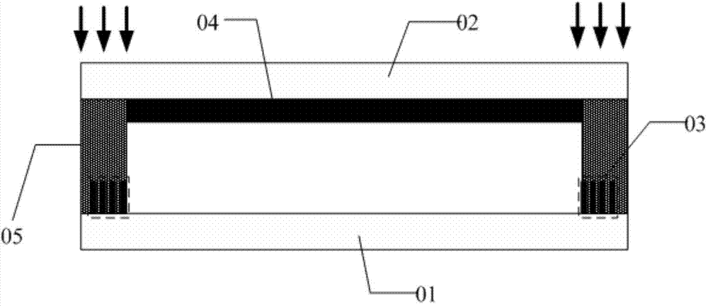
[0033] An embodiment of the present invention also provides a display panel, such as figure 2 As shown, the display panel includes an array substrate 01 and an opposite substrate 02 arranged oppositely; wherein,

[0034] The pattern of the drive circuit 03 and peripheral wiring (not shown in the figure) is provided in the frame area of ​​the side of the array substrate 01 facing the opposite substrate 02, and the side of the array substrate 01 facing the opposite substrate 02 and / or the opposite substrate 02 faces One side of the...


PUM


Abstract

The invention discloses a display panel and a manufacturing method thereof and a display device. Orthographic projection of a drive circuit in a border area and a graph with periphery wires on an array substrate is not overlapped with orthographic projection of a graph of a black matrix in the array substrate, in other words, no black matrixes are arranged in the area where the drive circuit and the graph with the wires are located; therefore, shielding of the black matrixes on ultraviolet light does not needed to be considered, the area where the drive circuit is located and gap width among the periphery wires can be reduced, the width of the border area is reduced, and narrow border design of the display panel is realized; in addition, a border sealing adhesive contains substances formed after discoloration of thermochromism materials with preset concentration during the curing process, so that the border sealing adhesive itself can achieve the effect of preventing the display panel from light leak after the curing treatment although no black matrixes are arranged in the area, where the drive circuit and the graph with the periphery wires are located, of the display panel.

Description

technical field [0001] The invention relates to the field of display technology, in particular to a display panel, a manufacturing method and a display device. Background technique [0002] Today, narrow bezel design has become an important trend in the development of the display field. Because of its beautiful design and low cost, it plays a very central role in large-size splicing design. Therefore, many display device manufacturers are pursuing narrow bezel design. [0003] At present, most display products are Gate Driver on Array (GOA) products, that is, GOA driving circuits for driving gate lines are distributed in the frame areas on the left and right sides of the array substrate of the display panel, and in the frame area There are generally some peripheral traces distributed. [0004] Specifically, the structure of the existing display panel is as figure 1 As shown, it includes an array substrate 1 and a color filter substrate 2, and the array substrate 1 is provi...

Claims


Application Information

Patent Timeline
Patent Type & Authority Applications(China)
IPC IPC(8): G02F1/01
CPCG02F1/1339G02F1/136209C09J11/02G02F1/133512G02F1/13454C08K3/38C08K5/18C09J2301/408G02F1/1335G02F1/1341C09J11/04C09J11/06C09J2203/326H05K5/0017H05K5/062
Inventor 肖文俊陈小川李月
Owner BOE TECH GRP CO LTD
Why Eureka
Try Eureka