
Energy-saving type roadside monitoring equipment

A technology for monitoring equipment and roadside monitoring base stations, which is applied to ticketing equipment, mechanical equipment, lighting and heating equipment, etc. It can solve the problems of lack of identification and recording base stations, so as to reduce the use time of air conditioners, reduce the waste of electric energy, and reduce the use of amount of effect

Inactive Publication Date: 2015-06-24
CHENGDU RUIYI INFORMATION TECH
View PDF7 Cites 3 Cited by
  • Summary
  • Abstract
  • Description
  • Claims
  • Application Information

AI Technical Summary

Problems solved by technology

[0003] In today's road network monitoring system, for ETC users' vehicles, there is a lack of base stations for identifying and recording the vehicle's driving path. At the same time, the base station cannot choose to turn on the air conditioner or fan to keep the temperature inside the base station constant according to the change of internal and external temperature. To ensure the best working condition of the base station, use the least power

Method used


Image

  • Energy-saving type roadside monitoring equipment

Examples


Embodiment 1

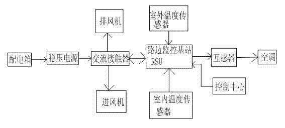
[0017] like figure 1 As shown, the present invention includes a distribution box, a stabilized power supply, a control center, an AC contactor and a roadside monitoring base station RSU connected in sequence, and an exhaust fan and an air intake fan are also connected on the described AC contactor; the roadside monitoring base station RSU can receive information, and can write path coding information to the extended electronic label OBU; The control center is connected to the roadside monitoring base station RSU, and the outdoor temperature sensor, indoor temperature sensor and mutual inductance sensor are also connected to the roadside monitoring base station RSU. The transformer is also connected to the air conditioner.

[0018] The power provided by the power distribution box in this scheme is processed by the stabilized power supply first, and then through the action of the AC contactor, it is supplied to the roadside monitoring base station RSU to work, so as to realize t...

Embodiment 2

[0020] This embodiment is preferred on the basis of Embodiment 1: the model of the AC contactor is CJ19-25 series. This series of AC contactors are more durable.

[0021] The roadside monitoring base station RSU is a roadside monitoring base station RSU of lightning protection and photoelectric isolation protection type. Prevent the roadside monitoring base station RSU from being damaged by lightning.

[0022] The roadside monitoring base station RSU includes a transceiver antenna and a controller connected to each other.

[0023] The control center is a computer terminal. Utilize computer control whether to open two fan or air conditioner.


PUM


Abstract

The invention discloses energy-saving type roadside monitoring equipment which comprises a distribution box, a stabilized voltage supply, a control center, an alternating current contactor and a roadside monitoring base station RSU. The alternating current contactor is further connected with an exhaust fan and an intake fan; the roadside monitoring base station RSU can receive information and write path coding information into an extended type electronic tag OBU; the control center is connected to the roadside monitoring base station RSU, the roadside monitoring base station RSU is further connected with an outdoor temperature sensor, an indoor temperature sensor and a mutual inductor, and the mutual inductor is further connected with an air conditioner. According to the above structure, the energy-saving type roadside monitoring equipment specially monitors vehicle traveling paths and records path coding information, meanwhile, when the temperature difference between the inside and the outside of the roadside monitoring base station RSU is changed, a draught fan or the air conditioner can be correspondingly selected to work, and on the premise that the optimal working condition of the roadside monitoring base station RSU is guaranteed, the reduction of the electric energy usage amount is maximized.

Description

technical field [0001] The invention relates to the field of high-speed road network monitoring, in particular to energy-saving roadside monitoring equipment. Background technique [0002] On December 26, 2014, Expressway Electronic Toll Collection (ETC) was successfully implemented in 14 provinces and cities including Beijing, Tianjin, Hebei, Shanxi, Liaoning, Shanghai, Jiangsu, Zhejiang, Anhui, Fujian, Jiangxi, Shandong, Hunan, and Shaanxi. Realized network operation. At present, the national ETC-connected provinces and cities have reached 52,000 kilometers of expressways, which is close to half of the total mileage of national expressways; 6,659 ETC-dedicated lanes have been built, an increase of 37% compared with the beginning of 2014; 718 self-operated customer service outlets have been established. There are 5,504 agency outlets and nearly 18,000 service terminals of various types; 9.09 million ETC users have been developed, an increase of 52% compared with the beginn...

Claims


Application Information

Patent Timeline
Patent Type & Authority Applications(China)
IPC IPC(8): G07B15/06F24F11/02
CPCG07B15/06F24F11/30F24F11/70F24F2110/10F24F2110/12
Inventor 梁海俊王梓涵张茜
Owner CHENGDU RUIYI INFORMATION TECH
Learn More