Method for manufacturing shell of motor

A technology for motors and casings, which is applied in the field of manufacturing motor casings for motors, and can solve problems such as high cost and poor sealing performance

Inactive Publication Date: 2015-06-24
ROBERT BOSCH GMBH
View PDF3 Cites 3 Cited by
  • Summary
  • Abstract
  • Description
  • Claims
  • Application Information

AI Technical Summary

Problems solved by technology

Correspondingly, the design of the motor housing is relatively costly in terms of construction.
Furthermore, there is the risk that the tightness between the base housing and the cover will deteriorate over the service life of the electric machine due to mechanical and climatic influences

Method used


Image

  • Method for manufacturing shell of motor
  • Method for manufacturing shell of motor

Examples


Embodiment Construction

[0022] The advantage of a tubular base shell is that it can be designed as a stretched or extruded tube, which can be produced cost-effectively.

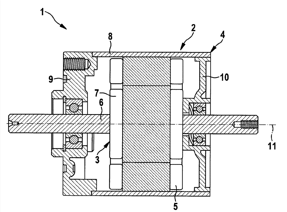
[0023] exist figure 1 An electric motor 1 is shown in longitudinal section, which is designed as an internal mover motor and comprises a stator 2 and an inner rotor 3 . Both belong to the stator 2 , as well as the stator part 5 arranged on the inner side of the motor housing 4 and which excites the magnetic field, which is designed either as a permanent magnet or as an energizable coil. A motor shaft 6 , which is rotatably mounted in the motor housing 4 , and an armature assembly 7 placed on the motor shaft 6 , which has coils which are energized via a rectifier, belong to the rotor 3 .

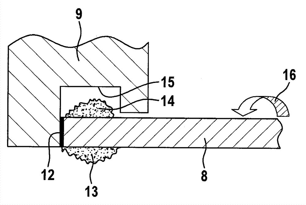
[0024] The motor housing 4 is constructed in multiple parts and comprises a cylindrical, tubular base housing 8 and two covers 9 and 10 arranged on the end faces of the base housing 8 . The covers 9 and 10 are joined to the base shell 8 in a fric...


PUM


Abstract

The invention relates to a method for manufacturing the shell of a motor, wherein a cylinderial base shell and a cover at the opened end portion of the base shell are mutually connected through the friction welding process.

Description

technical field [0001] The invention relates to a method for producing a motor housing for an electric machine. Background technique [0002] It is known that the housing of the electric machine is designed either in two parts with a pot-shaped base housing and a cover, or in three parts with a cylindrical tube and two end covers, wherein the housing accommodates the stator or is part of the stator. During assembly, the cover must be fixed on the end face of the cylindrical base housing, wherein in order to achieve a tight closure, a surrounding sealing element must be arranged in the connecting region between the base housing and the cover, the surrounding The sealing element is accommodated in a correspondingly configured geometry on the base housing or on the cover. Correspondingly, the design of the motor housing is relatively complex in terms of construction. Furthermore, there is the risk that the tightness between the base housing and the cover will deteriorate ove...

Claims


Application Information

Patent Timeline
Patent Type & Authority Applications(China)
IPC IPC(8): H02K5/04H02K15/14B23K20/12
CPCB23K20/129H02K5/15H02K15/14B23K20/12
Inventor S.奥弗迈尔M.埃尔默
Owner ROBERT BOSCH GMBH
Why Eureka
Try Eureka