Control method and system for permanent magnet synchronous motor

A permanent magnet synchronous motor and control method technology, applied in control systems, vector control systems, motor generator control and other directions, can solve problems such as motor faults and current oscillations, improve stability, avoid current oscillations, and eliminate current inconsistencies. Effects of stabilization problems

Inactive Publication Date: 2015-06-24
CSR ZHUZHOU ELECTRIC LOCOMOTIVE RES INST
View PDF5 Cites 23 Cited by
  • Summary
  • Abstract
  • Description
  • Claims
  • Application Information

AI Technical Summary

Problems solved by technology

This method realizes the transition from zone 1 to zone 2, but when the given current is large, and when the permanent

Method used


Image

  • Control method and system for permanent magnet synchronous motor
  • Control method and system for permanent magnet synchronous motor
  • Control method and system for permanent magnet synchronous motor

Examples


Embodiment Construction

[0057] The following will clearly and completely describe the technical solutions in the embodiments of the application with reference to the drawings in the embodiments of the application. Apparently, the described embodiments are only some of the embodiments of the application, not all of them. Based on the embodiments in this application, all other embodiments obtained by persons of ordinary skill in the art without creative efforts fall within the protection scope of this application.

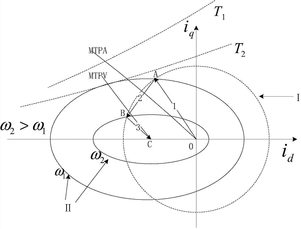
[0058] The maximum torque-to-voltage ratio refers to the minimum stator voltage at which the maximum speed can be achieved under the same torque output condition. The maximum torque-voltage ratio locus is a curve connecting the minimum voltage points required to produce different torque values, that is, the line connecting the voltage limit circle and the tangent point of the torque hyperbola, such as figure 1 As shown in the BC segment curve in , its equation can be expressed as:

[0059]...


PUM


Abstract

The invention provides a control method and system for a permanent magnet synchronous motor. The control method and system are characterized in that firstly, initial given currents are obtained according to the given angular speed and the actual angular speed of the permanent magnet synchronous motor; initial quadrature-axis currents are obtained according to the initial given currents; initial direct-axis currents are obtained according to the initial given currents; first direct-axis currents are obtained according to the initial direct-axis currents and the negative compensation quantity; second direct-axis currents are obtained according to the first direct-axis currents, and the second direct-axis currents are not smaller than a preset lower limit value; given direct-axis voltages are obtained according to the second direct-axis currents; the difference between the first direct-axis currents and the second direct-axis currents is acquired, ratio calculation is conducted on the differencing result, and the quadrature-axis current compensation quantity is acquired through calculation; the difference between the initial quadrature-axis currents and the quadrature-axis current compensation quantity, and first quadrature-axis currents are obtained; given quadrature-axis voltages are obtained according to the first quadrature-axis currents; the negative compensation quantity is acquired according to the given quadrature-axis currents and the given quadrature-axis voltages. The stability of the permanent magnet synchronous motor can be improved, and current oscillation is avoided.

Description

technical field [0001] The present application relates to the technical field of motor drive, and more specifically, to a control method and system for a permanent magnet synchronous motor. Background technique [0002] The excitation magnetomotive force of the permanent magnet synchronous motor is generated by the permanent magnet and cannot be adjusted. It can only be adjusted by reducing the direct axis current i of the motor d and quadrature current i q To achieve the purpose of magnetic field-weakening expansion. As far as the current field weakening control strategy is concerned, on the one hand, it only realizes the smooth transition between the maximum torque current ratio and the current limit circle, but does not realize the smooth transition between the current limit circle and the maximum torque voltage ratio; on the other hand , when the given current is large and the field is deeply weakened, it is easy to cause current oscillation, which makes the control sy...

Claims


Application Information

Patent Timeline
IPC IPC(8): H02P21/00
Inventor 冯江华许峻峰石敏何亚屏张朝阳肖磊文宇良刘雄
Owner CSR ZHUZHOU ELECTRIC LOCOMOTIVE RES INST
Why Eureka
Try Eureka