TP lens alignment device and method applied to terminal
A centering device and lens technology, which is applied in the field of communication, can solve the problems of easily scratched terminal appearance and long working hours, and achieve the effects of saving working time, simple operation and avoiding injuries
- Summary
- Abstract
- Description
- Claims
- Application Information
AI Technical Summary
Problems solved by technology
Method used
Image

Examples
Embodiment 1
[0079] Since the size of the TP lens is known and the size of the front shell assembly used to install the TP lens on the mobile terminal is known, the centering position of the TP lens on the front shell assembly and the position of the TP lens in the centering position can be accurately calculated. The distance between its surroundings and the surroundings of the front shell assembly (hereinafter referred to as the preset clearance value). This embodiment is implemented based on the preset gap value.
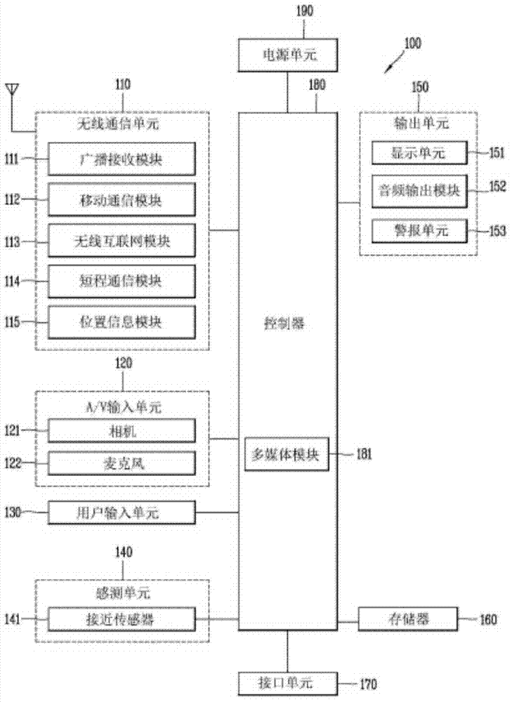
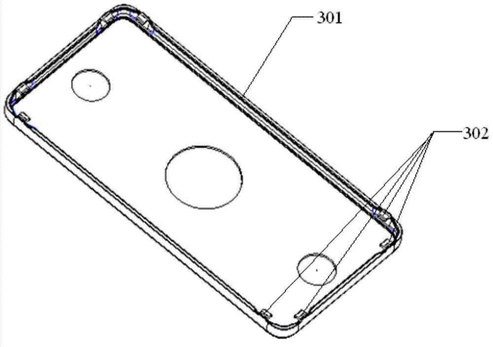
[0080] for figure 1 In the mobile terminal shown, in order to accurately realize the centering of its TP lens, this embodiment proposes a TP lens centering device 300, such as image 3 with Figure 4 shown, including:
[0081] The plastic body 301 includes a left side, a right side, an upper side, a right side and a rear wall, and the four sides form an accommodating space, which has the same size and structure as the front shell assembly of the mobile terminal. Matching, ...
Embodiment 2
[0091] In the first embodiment, on the plastic body 301 of the TP lens centering device 300, there are two limit structures 302 on each side, so there are eight limit structures 302 on the whole device 300, so that no matter The precise positioning of the TP lens can be achieved by operating from any direction.
[0092] However, in the actual operation process, it is only necessary to determine the positions of the adjacent two sides to accurately position the TP lens. Therefore, in this embodiment, on the premise of ensuring the realization of basic functions, in order to reduce costs, only the plastic body 301 A limiting structure 302 is respectively provided on two adjacent sides, and the TP lens can be positioned only by abutting the sides of the TP lens against the corresponding limiting structures 302 during operation.
[0093] In this embodiment, the structure of the TP lens centering device 300 is further simplified and the cost is reduced.
Embodiment 3
[0095] In Embodiment 1, the size of the plastic body 301 matches the size of the front shell assembly of the mobile terminal, and the front shell assembly can be completely put into the plastic body 301, which is more convenient to operate, but the size of the plastic body 301 is relatively large, and the cost higher.
[0096] In the third embodiment, in order to reduce the cost, the plastic body 301 adopts Image 6 The structure shown is only image 3 The upper half of the structure shown.
[0097] In application, it is basically the same as the first embodiment: first, the plastic body 301 is sleeved on the upper part of the front case assembly of the mobile terminal, and then the TP lens is positioned against the limiting structure 302 .
[0098] By applying the third embodiment, the production cost can be reduced, and the accurate centering of the TP lens can be realized.
PUM
 Abstract
Description
Claims
Application Information
PatSnap Eureka turns technology decisions into work you can execute. Powered by our Innovation Knowledge Graph, it runs expert workflows across engineering, life sciences, materials and intellectual property. Get your review-ready output in minutes.


