
Radiation testing method for simulation television station transmitting power under open ground environment

A technology of transmitting power and testing method, which is applied in the direction of television, electrical components, image communication, etc. It can solve the problem of missing, unable to examine the influence of the antenna-feeder system on the actual radiation characteristics of the station, and the transmitter does not have a coupling port or coupling port coupling. parameters and other issues to achieve the effect of improving flexibility and autonomy

Inactive Publication Date: 2015-06-24
国家无线电监测中心 +2
View PDF1 Cites 2 Cited by
  • Summary
  • Abstract
  • Description
  • Claims
  • Application Information

AI Technical Summary

Problems solved by technology

This traditional conduction test method is not only unable to investigate the influence of the antenna feed system on the actual radiation characteristics of the station, but also often cannot be carried out because the transmitter of the station does not have a coupling port or the coupling parameters of the coupling port are missing.
In addition, from the perspective of the actual effect of radio monitoring, because the traditional conduction test method requires the coordination and cooperation of multiple departments such as testing institutions and stations, the timeliness, flexibility and autonomy of monitoring work will also be affected.

Method used


Image

  • Radiation testing method for simulation television station transmitting power under open ground environment
  • Radiation testing method for simulation television station transmitting power under open ground environment
  • Radiation testing method for simulation television station transmitting power under open ground environment

Examples


Embodiment Construction

[0024] The present invention will be described in detail below in conjunction with the accompanying drawings.

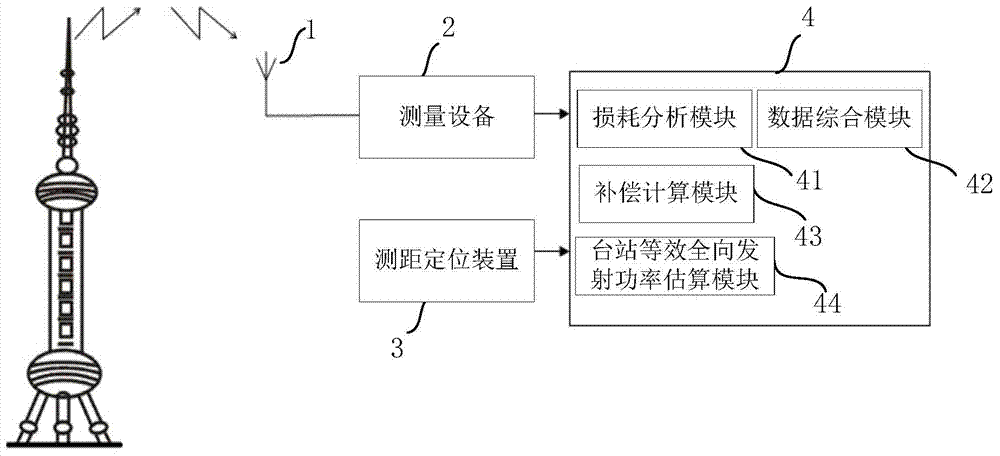
[0025] figure 1 It is a compositional block diagram of a radiation test system for simulating the transmitting power of a TV station in an open ground environment provided by the present invention. Such as figure 1 As shown, the radiation test system for simulating the transmitting power of a TV station station in an open ground environment provided by the present invention includes: a directional receiving antenna 1 (for example: a logarithmic period antenna), a power measurement device 2 (for example: a spectrum analyzer, a power meter), a measuring Distance and positioning device 3 (for example: laser rangefinder, GPS receiver) and control device 4 (for example: computer, handheld mobile terminal, etc.).

[0026] The directional receiving antenna 1 is used to receive the electromagnetic wave emitted by the analog TV station in an open ground environment and conv...


PUM


Abstract

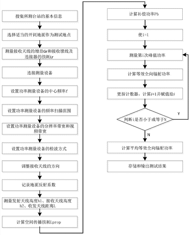
The invention provides a radiation testing method for simulation television station transmitting power under an open ground environment, and belongs to the field of radio transmission system performance index testing. The testing method comprises the steps that a center frequency f of power measurement equipment is set; the polarization direction and the pitching direction of a receiving antenna are adjusted, and after a signal maximum value is found, the receiving antenna is fixed; the height h1 of a transmitting antenna, the height h2 of the receiving antenna and the distance L between the receiving antenna and the transmitting antenna are measured and recorded; the peak power Pr received by the receiving antenna is measured; the equivalent isotropic radiated power (EIRP) of a tested station is calculated according to the following formula: EIRP=Pr-Gr+Lr+Lprop+Pb, wherein the Gr is the gain of the receiving antenna, the Lr is the loss of a receiving feeder line and a connector, the Lprop is space transmission loss, and the Pb is compensation power. The radiation testing method for the simulation television station transmitting power under the open ground environment can achieve more comprehensive and accurate monitoring on a station radio transmission system including transmitters and antenna feed systems, and therefore the working flexibility and autonomy are greatly improved.

Description

technical field [0001] The invention provides a radiation test method for simulating the transmit power of a TV station in an open ground environment, and belongs to the field of performance index test of a radio transmission system. Background technique [0002] In the prior art, the test of the transmitting power of the analog TV station is mainly conducted through conduction. The transmitter of the station outputs the RF power to the input terminal of the test equipment through the coupling port, and the transmission power of the transmitter can be calculated according to the coupling power and coupling coefficient received by the test equipment. This traditional conduction test method is not only unable to investigate the influence of the antenna feed system on the actual radiation characteristics of the station, but also often cannot be carried out because the transmitter of the station does not have a coupling port or the coupling parameters of the coupling port are mi...

Claims


Application Information

Patent Timeline
Patent Type & Authority Applications(China)
IPC IPC(8): H04N17/00
Inventor 张科刘璇王文俭李吉曲晟明张莎范志平祁超汪志斌
Owner 国家无线电监测中心
Learn More