Passive optical network, device and method for adjusting logical splitting ratio of optical branching device

A passive optical network, optical splitter technology, applied in the field of mobile communication, can solve problems such as consumption, tight power budget, distance difference, etc.

Inactive Publication Date: 2015-06-24
CHINA MOBILE COMM GRP CO LTD
View PDF5 Cites 12 Cited by
  • Summary
  • Abstract
  • Description
  • Claims
  • Application Information

AI Technical Summary

Problems solved by technology

In the existing technology, for scenarios where the number of users increases, optical splitters can be newly deployed, but this solution needs to consume more valuable backbone access fibers; in the existing technology, it can also be deployed directly during the initial deployment An optical splitter with a large splitting ratio, but this solution will result in that although the optical splitter ports are used less in a large number of scenarios, the uplink and downlink insertion losses are still large splitting ratio insertion losses, resulting in tight power budgets
[

Method used


Image

  • Passive optical network, device and method for adjusting logical splitting ratio of optical branching device
  • Passive optical network, device and method for adjusting logical splitting ratio of optical branching device
  • Passive optical network, device and method for adjusting logical splitting ratio of optical branching device

Examples


Embodiment Construction

[0085] In order to make the technical solutions and advantages of the present invention clearer, the present invention will be further described in detail below in conjunction with the accompanying drawings and specific embodiments.

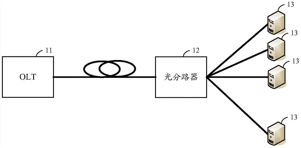
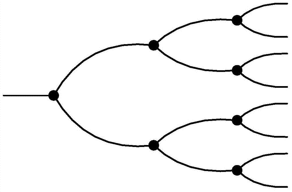
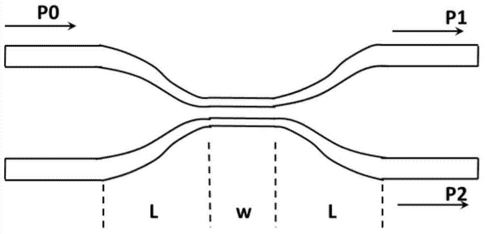
[0086] In the dynamically reconfigurable passive optical network proposed by the present invention, it is necessary to use an optical splitter with a dynamically adjustable splitting ratio, and the optical splitter generally consists of multi-stage 1×2 optical coupling units through cascaded Therefore, in the present invention, three kinds of optical coupling units with dynamically adjustable splitting ratio as described below can be used to realize an optical splitter with dynamically adjustable splitting ratio, and the above-mentioned dynamically adjustable splitting ratio can be used The optical splitter is used to form a dynamically reconfigurable passive optical network.

[0087] The three types of optical coupling units with dynamically adj...


PUM


Abstract

The invention provides a passive optical network, device and method for adjusting logical splitting ratio of an optical branching device. The passive optical network comprises an OLT, the optical branching device, multiple ONUs and optical fibers connected among the OLT, the optical branching device and the multiple ONUs; the OLT is used for detecting the physical splitting ratio and the logical splitting ratio of the passive optical branching device, the OLT and the system parameters of the ONUs in real time, monitoring commands are transmitted to each ONU through the optical branching device, and motoring results returned by the ONUs are received through the optical branching device; according to the physical splitting ratio and the logical splitting ratio of the passive optical branching device, the OLT, the system parameters of the ONUs and the monitoring results returned by the ONUs, the wave length of an optical signal is adjusted for changing the logical splitting ratio of the optical branching device; the ONUs are used for conducting monitoring according to the received motoring commands and transmitting the monitoring results to the OLT through the optical branching device. By the application of the passive optical network, device and method for adjusting the logical splitting ratio of the optical branching device, the dynamic reconfiguration of the passive optical network can be achieved.

Description

technical field [0001] The present application relates to the technical field of mobile communication, and in particular to a dynamically reconfigurable passive optical network, a device and a method for adjusting the logic splitting ratio of an optical splitter. Background technique [0002] In the existing technology, the passive optical network (PON) technology is the mainstream technology for realizing fiber access (FTTx). figure 1 is a schematic structural diagram of a passive optical network in the prior art, such as figure 1 As shown, a typical PON system is generally composed of an optical line terminal (OLT) 11 at the central office, an optical network unit (ONU) 13 at the user end, and an optical distribution network (ODN). The "passive" in the ODN refers to It does not contain any active electronic devices and electronic power sources, and is entirely composed of passive optical devices such as optical fibers and optical splitters / combiners (Splitter) 12 . [00...

Claims


Application Information

Patent Timeline
IPC IPC(8): H04Q11/00H04B10/07
Inventor 李晗黄晓庆张德朝王磊韩柳燕程伟强柳晟
Owner CHINA MOBILE COMM GRP CO LTD
Why Eureka
Try Eureka