an optical splitter

An optical splitter and evenly divided technology, applied in the field of mobile communication, can solve the problems of waste, tight power budget, consumption, etc., and achieve the effect of reducing equipment costs, operation and maintenance costs, and types

Active Publication Date: 2017-02-22
CHINA MOBILE COMM GRP CO LTD
View PDF9 Cites 0 Cited by
  • Summary
  • Abstract
  • Description
  • Claims
  • Application Information

AI Technical Summary

Problems solved by technology

In the existing technology, for scenarios where the number of users increases, optical splitters can be newly deployed, but this solution needs to consume more valuable backbone access fibers; in the existing technology, it can also be deployed directly during the initial deployment An optical splitter with a large splitting ratio, but this solution will result in that although the optical splitter ports are used less in a large number of scenarios, the uplink and downlink insertion losses are still large splitting ratio insertion losses, resulting in tight power budgets
[0007] 3. There is a big difference in the distance of different users under a single PON port, or there is a big difference in the link loss of different distribution fibers (such as the bending loss during deployment and construction, etc.), so the power budget can only be calculated according to the worst link. Therefore, it will cause a waste of power budget for links with shorter distances or less loss, and may even cause power overload problems. At the same time, it also poses challenges to the automatic gain control (AGC) of the optical line terminal (OLT) receiver.

Method used


Image

  • an optical splitter
  • an optical splitter
  • an optical splitter

Examples


Embodiment Construction

[0030] In order to make the technical solutions and advantages of the present invention clearer, the present invention will be further described in detail below in conjunction with the accompanying drawings and specific embodiments.

[0031] According to the working principle, optical splitters can generally be divided into two types: fused biconical taper (FBT, Fused Biconical Taper) optical splitters and planar waveguide (PLC) optical splitters, and multiple optical splitters can also be Connect in cascade to form a large optical splitter.

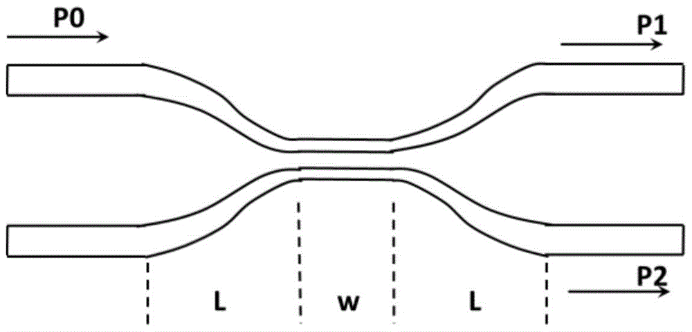
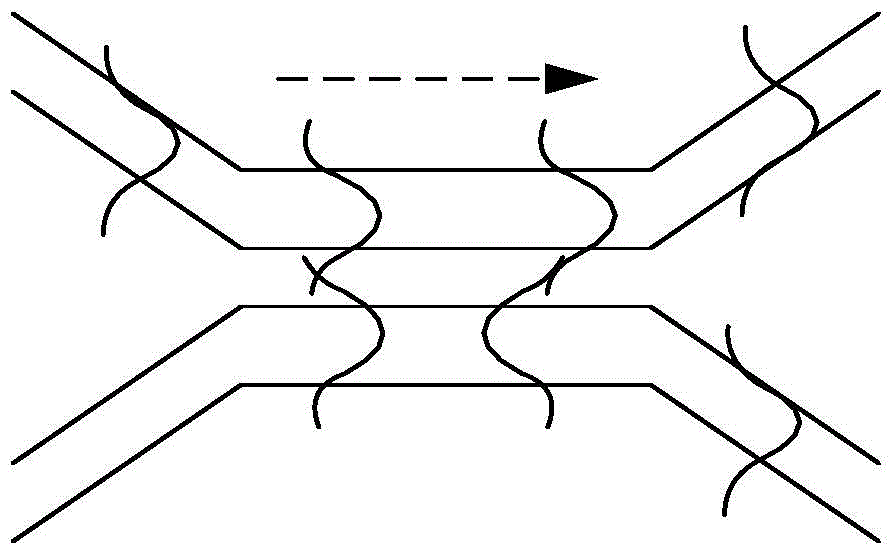
[0032] figure 2 It is a schematic structural diagram of a fused tapered optical splitter in an embodiment of the present invention. Such as figure 2 As shown, the fusion tapered optical splitter is to bring two (or more than two) optical fibers whose coating layer has been removed to close together in a certain way, melt under high temperature heating, and stretch to both sides at the same time, and finally in the heating zone A spe...


PUM


Abstract

The invention provides an optical divider. The optical divider comprises an input port, two output ports and a coupling area arranged between the input port and the output ports, wherein the ratio of the output light power of a single output end of the optical diver to the total output light power periodically changes along with changes of wavelengths of optical waves within an assigned wavelength range. Due to the application of the optical divider, the splitting ratio of the optical divider can be dynamically adjustable in many cycles.

Description

technical field [0001] The present application relates to the technical field of mobile communication, in particular to an optical splitter. Background technique [0002] In the existing technology, the passive optical network (PON) technology is the mainstream technology for realizing fiber access (FTTx). figure 1 is a schematic structural diagram of a passive optical network in the prior art, such as figure 1 As shown, the topology of a typical PON system is generally a tree topology, which is generally composed of an optical line terminal (OLT) at the central office equipment, an optical network unit (ONU) at the user end equipment, and an optical distribution network (ODN). "Passive" means that the ODN does not contain any active electronic devices and electronic power sources, and is all composed of passive optical devices such as optical fibers and optical splitters / combiners (Splitter). The ODN generally consists of optical fibers and optical splitters / combiners. an...

Claims


Application Information

Patent Timeline
Patent Type & Authority Patents(China)
IPC IPC(8): G02B6/38
CPCG02B6/125G02B2006/1215
Inventor 李晗柳晟王磊张德朝李允博韩柳燕程伟强叶雯王世光李遥
Owner CHINA MOBILE COMM GRP CO LTD
Why Eureka
Try Eureka