Liquid crystal composition, liquid crystal display element, and liquid crystal display
A technology of liquid crystal display element and liquid crystal composition, which is applied in the direction of liquid crystal materials, instruments, chemical instruments and methods, etc., which can solve the problems of insufficient drop mark suppression effect, etc., and achieve good characteristics, less occurrence of screen burn-in, and less drop marks Effect
- Summary
- Abstract
- Description
- Claims
- Application Information
AI Technical Summary
Problems solved by technology
Method used
Image
Examples
Embodiment 1
[0253] [Example 1, Comparative Example 1]
[0254] Liquid crystal compositions having the compositions shown in Table 1 were prepared, and their physical properties were measured.
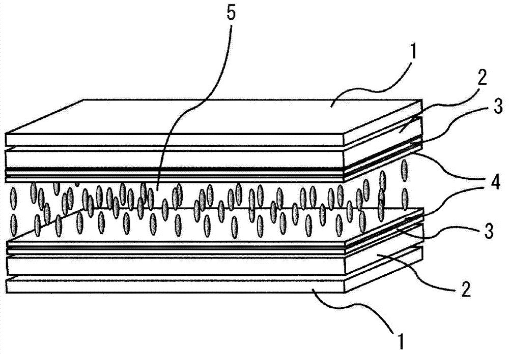
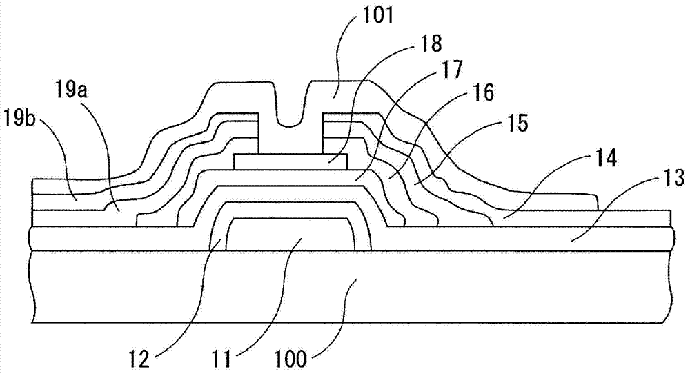
[0255] In addition, using the liquid crystal compositions of Example 1 and Comparative Example 1, respectively figure 1 The VA liquid crystal display element shown. This liquid crystal display element has a reverse-stacked thin film transistor as an active element. The injection of the liquid crystal composition was performed by the dropping method (ODF method). Further, the obtained display element was evaluated for burn-in, drop marks, process adaptability and solubility at low temperature by the aforementioned method. The results are shown in Table 2.
[0256] [Table 1]
[0257]
[0258] In Table 1, the compound represented by the chemical formula (b4) of Comparative Example 1 is a compound represented by the structural formula of the following formula (b4).
[0259] [chem 29]
[0260]...
Embodiment 2
[0264] [Example 2, Comparative Example 2]
[0265] Liquid crystal compositions having the compositions shown in Table 3 were prepared, and their physical properties were measured.
[0266] In addition, for the display elements produced in the same manner as in Example 1 using the liquid crystal compositions of Example 2 and Comparative Example 2, evaluations of burn-in, drop marks, process suitability, and solubility at low temperatures were performed. The results are shown in Table 4.
[0267] [table 3]
[0268]
[0269] [Table 4]
[0270]
[0271] The liquid crystal composition of Example 2 has a liquid crystal phase temperature range of 87.3° C. which is practical as a liquid crystal composition for TV, and also has good refractive index anisotropy and dielectric constant anisotropy. In addition, it is also excellent in solubility at low temperature. Further, using the liquid crystal composition of Example 2 to produce figure 1 The VA liquid crystal disp...
Embodiment 3~6
[0273] Liquid crystal compositions having the compositions shown in Table 5 were prepared, and their physical properties were measured.
[0274] In addition, for the display elements produced in the same manner as in Example 1 using the liquid crystal compositions of Examples 3 to 6, evaluations of burn-in, drop marks, process suitability, and solubility at low temperatures were performed. The results are shown in Table 6.
[0275] [table 5]
[0276]
[0277] [Table 6]
[0278]
PUM
| Property | Measurement | Unit |
|---|---|---|
| viscosity | aaaaa | aaaaa |
| electrical resistivity | aaaaa | aaaaa |
| thickness | aaaaa | aaaaa |
Abstract
Description
Claims
Application Information
 - R&D
- Intellectual Property
- Life Sciences
- Materials
- Tech Scout
- Unparalleled Data Quality
- Higher Quality Content
- 60% Fewer Hallucinations
Browse by: Latest US Patents, China's latest patents, Technical Efficacy Thesaurus, Application Domain, Technology Topic, Popular Technical Reports.
© 2025 PatSnap. All rights reserved.Legal|Privacy policy|Modern Slavery Act Transparency Statement|Sitemap|About US| Contact US: help@patsnap.com


