Step milling cutter

A milling cutter and step technology, which is applied in the field of step milling cutters, can solve the problems of low efficiency of large planes of rod milling cutters, and achieve the effects of saving labor, improving processing efficiency, and fast milling speed

Inactive Publication Date: 2015-07-01
武文斌
View PDF0 Cites 0 Cited by
  • Summary
  • Abstract
  • Description
  • Claims
  • Application Information

AI Technical Summary

Problems solved by technology

At present, the existing technology usually only uses rod milling cutters for processing, but the efficiency of processing large planes with rod milling cutters is too low when using this method

Method used


Image

  • Step milling cutter
  • Step milling cutter
  • Step milling cutter

Examples


Embodiment Construction

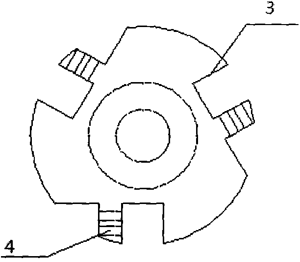
[0011] The principle and features of the present invention will be described below by taking the chassis having three installation grooves as an example, with reference to the accompanying drawings. The examples given are only for explaining the present invention, and are not intended to limit the scope of the present invention.

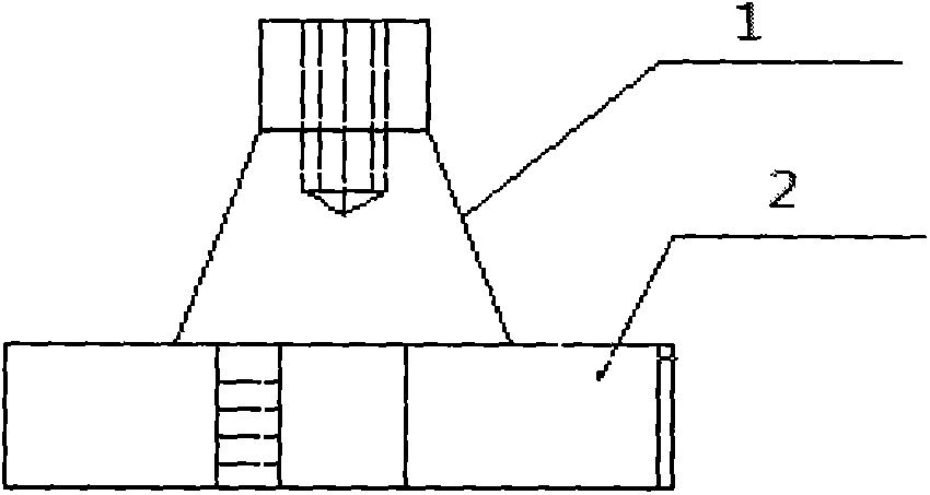
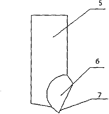
[0012] Such as figure 1 , figure 2 As shown, a step milling cutter includes a handle 1 and a chassis 2 connected to the handle 1 as a whole, and a knife bar 4. The chassis 2 is provided with a mounting groove 3 for installing the knife bar 4 and fixing the knife The top screw hole 4 of the handle 1, the other end of the knife rod 5 opposite to the knife handle 1 along the axial direction of the installation groove 3 is provided with a cutter head 6 with a knife tooth 7, it is characterized in that the The number of mounting slots 3 for installing the knife bar 4 on the chassis is 3, and the number of knife bars is 3. The axial positions of the knif...


PUM


Abstract

The invention discloses a step milling cutter, which comprises a knife handle, a base plate and 2-6 cutter bars, wherein the base plate and the cutter bars are connected with the knife handle 1 into a whole; 2-6 mounting grooves for mounting the cutter bars and a top thread hole for fixing the knife handle are formed in the base plate; a tool bit with cutter teeth is arranged at the other end, opposite to the knife handle, of each cutter bar along the axial direction of each mounting groove; the axial positions of the cutter bars in a cutter groove can be respectively adjusted; and cutting edges of the cuter bars can be located on a same plane, and can also be adjusted on different planes according to the cutting allowance. Through use of the step milling cutter disclosed by the invention, various workpices can reach high milling speeds in the milling process; time can be shortened; the labor force can be saved; and the processing efficiency of the workpices can be greatly improved.

Description

technical field [0001] The invention relates to a step milling cutter used in mechanical processing, in particular to a step milling cutter. Background technique [0002] In the machining process, milling can obtain planes, mesa, grooves, etc., and the methods and tools used are different according to the structure of the workpiece. As far as the processing of larger planes is concerned, end milling cutters can be used for end milling and cylindrical milling cutters can be used for horizontal milling. Although the milling machine we use has two functions of vertical milling and horizontal milling, some equipment accessories need to be disassembled and assembled during the conversion process between vertical milling and horizontal milling. ), can only expand the range of end milling. In the milling process of large planes, if end mills are used for milling, the purchased standard end mill blades are disposable and cannot be repaired, resulting in large tool loss and high co...

Claims


Application Information

Patent Timeline
Patent Type & Authority Applications(China)
IPC IPC(8): B23C5/20
CPCB23C5/20B23C2210/168B23C2210/247
Inventor 武文斌
Owner 武文斌
Why Eureka
Try Eureka