Hydraulic type tire vulcanizing machine with improved mold clamping structure

An improved tire vulcanization technology, which is applied in the field of hydraulic tire vulcanizers, can solve problems such as inconvenient space for maintenance, troublesome modification, and entry into the pit, and achieve the effect of overcoming the inconvenience of maintenance and repair

Inactive Publication Date: 2015-07-01
SINO ARP TIRES EQUIP TECH (SUZHOU) CO LTD
View PDF5 Cites 0 Cited by
  • Summary
  • Abstract
  • Description
  • Claims
  • Application Information

AI Technical Summary

Problems solved by technology

This has brought problems for existing hydraulic tire vulcanizers of this type, because key components such as its clamping mechanism and limit mechanism are all buried in the pit, and the parts of these mechanisms are many and complicated to connect. Periodic maintenance is required in normal use, which requires regular access to the pit, which is very troublesome to maintain, and the narrow space in the pit is not convenient for full-scale maintenance; when these mechanisms are damaged or have problems, maintenance It is also troublesome for personnel to modify these mechanisms; in addition, because the current clamping mechanism is installed under the lower beam, a limit mechanism needs to be installed between it and the lower beam to ensure the position of the lower beam and other components. complex

Method used


Image

  • Hydraulic type tire vulcanizing machine with improved mold clamping structure
  • Hydraulic type tire vulcanizing machine with improved mold clamping structure
  • Hydraulic type tire vulcanizing machine with improved mold clamping structure

Examples


Embodiment Construction

[0024] Preferred embodiments of the present invention will be described in detail below in conjunction with the accompanying drawings.

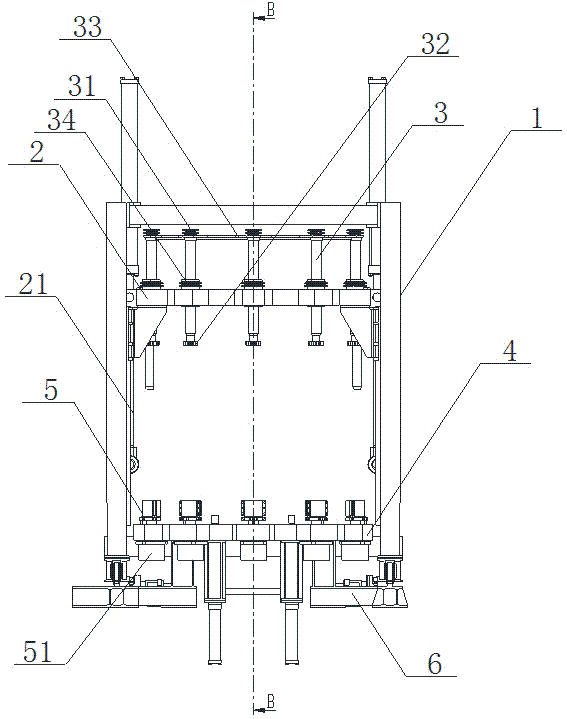
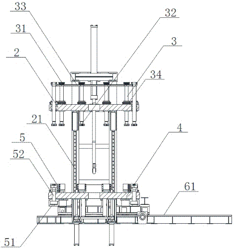
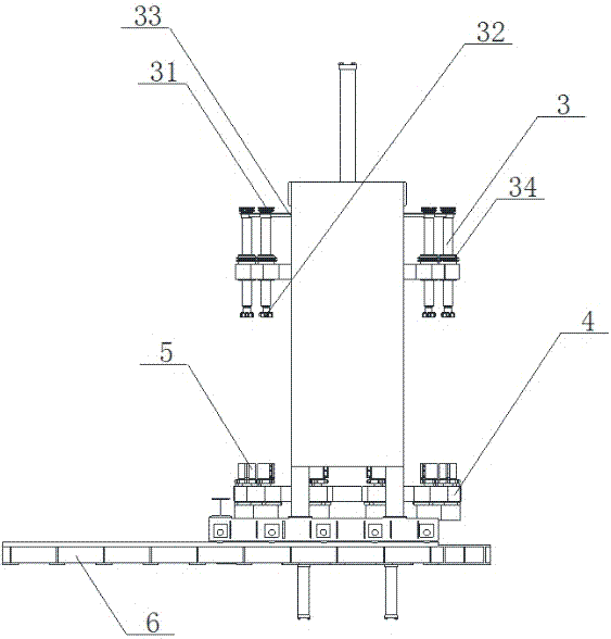
[0025] In the first embodiment of the hydraulic tire vulcanizing machine with improved clamping structure involved in the present invention, as Figure 1-5 As shown, it includes: a frame 1; an upper beam 2, which is arranged in the frame 1, and moves up and down in the frame 1 through a driving device 21. The driving device 21 can be driven by a motor and a pulley, except of course In addition, methods such as leading screws and guide rails known in the prior art can also be used. The upper beam 2 is also pierced with a plurality of tie rods 3 arranged equidistantly. The number of tie rods 3 should be adjusted according to the size of the tire. The number is not specifically limited here. The upper end of the pull rod 3 is provided with a first sprocket 31, and the transmission connection between the multiple first sprockets 31 is carried out...


PUM


Abstract

The invention discloses a hydraulic type tire vulcanizing machine with an improved mold clamping structure. The hydraulic type tire vulcanizing machine comprises a rack, an upper transverse beam and a lower transverse beam, wherein the upper transverse beam is arranged in the rack and moves up and down in the rack by virtue of a driving device; multiple pull rods arranged in equal distance penetrate through the upper transverse beam; first chain wheels are arranged at the upper ends of the pull rods; the multiple first chain wheels are in transmission connection with one another; first connecting parts are arranged at the lower ends of the pull rods; the lower transverse beam is parallel to the upper transverse beam and is fixedly arranged at the bottom of the rack; multiple second connecting parts are arranged at positions, which correspond to the first connecting parts, of the lower transverse beam; and the second connecting parts are in normal running fit with the first connecting parts. Compared with the prior art, the hydraulic type tire vulcanizing machine disclosed by the invention has the advantages that the arrangement position of a mold clamping mechanism is changed, the structure is simplified, and the defects that the maintenance is inconvenient and a limiting device needs to be arranged are overcome.

Description

technical field [0001] The invention relates to a hydraulic tire vulcanizer, in particular to a hydraulic tire vulcanizer with an improved clamping structure. Background technique [0002] The hydraulic tire curing press appeared along with the vigorous development of the automobile industry and its tire industry, and gradually replaced the original mechanical tire curing press with the development of technology, and became a kind of tire curing press that is widely used now. Compared with the traditional mechanical tire curing press, the hydraulic tire curing press has higher processing precision, and the tires produced by it can better meet the demand for better tires in the development of the modern automobile industry. Because of this, various hydraulic tire vulcanizing machines have appeared now, which has promoted technological progress in this field. [0003] The Chinese patent with the publication number CN203019589 discloses a hydraulic tire vulcanizing machine wit...

Claims


Application Information

Patent Timeline
Patent Type & Authority Applications(China)
IPC IPC(8): B29C33/20B29C35/00
Inventor 黄桂强黄福旺
Owner SINO ARP TIRES EQUIP TECH (SUZHOU) CO LTD
Why Eureka
Try Eureka