
A heavy-duty balance shaft assembly

A balance shaft, heavy load technology, applied in the direction of axle, elastic suspension, interconnection system, etc., can solve the problem of low reliability of the connection between the balance shaft assembly and the frame girder, the fracture of the bracket or the connecting bolt, and the aggravation of the wear of the single oil seal To achieve the effect of reducing maintenance service costs, reducing the risk of cracking failure, and excellent comprehensive mechanical properties

Active Publication Date: 2017-04-19
ANHUI ANKAI JINDA MACHINERY MFG
View PDF6 Cites 0 Cited by
  • Summary
  • Abstract
  • Description
  • Claims
  • Application Information

AI Technical Summary

Problems solved by technology

[0005] The shaft shells of some balance shaft assembly products still have quality problems of oil leakage. The oil leakage points mainly include the end cover and the oil seal.
In addition, a large amount of dust and small particles of sand enter the shaft housing cavity from the single oil seal, which intensifies the wear of the single oil seal. Once the single oil seal fails, the assembly will leak oil
[0006] In the existing assembly, the contact surface between the shaft belt bracket and the frame girder is a large plane, and the connection reliability between the balance shaft assembly and the frame girder is not high, and the risk of breakage of the bracket or connecting bolts is easy to occur

Method used


Image

  • A heavy-duty balance shaft assembly
  • A heavy-duty balance shaft assembly
  • A heavy-duty balance shaft assembly

Examples


Embodiment Construction

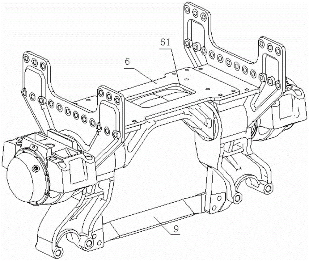
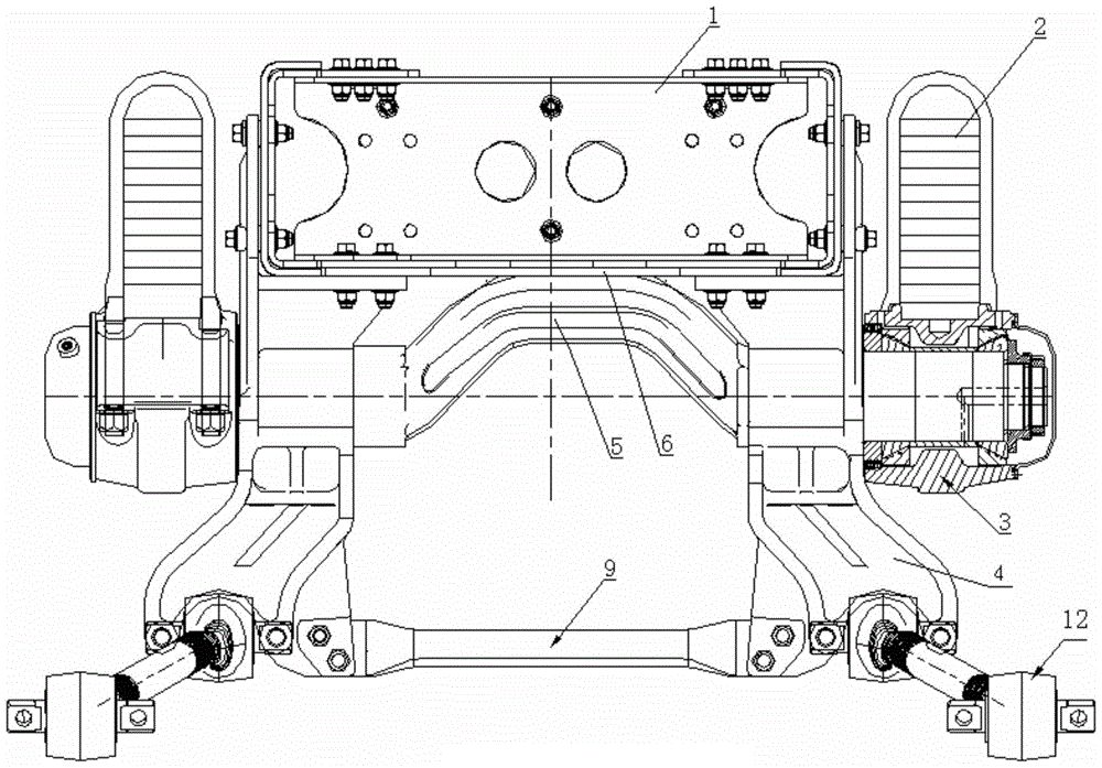
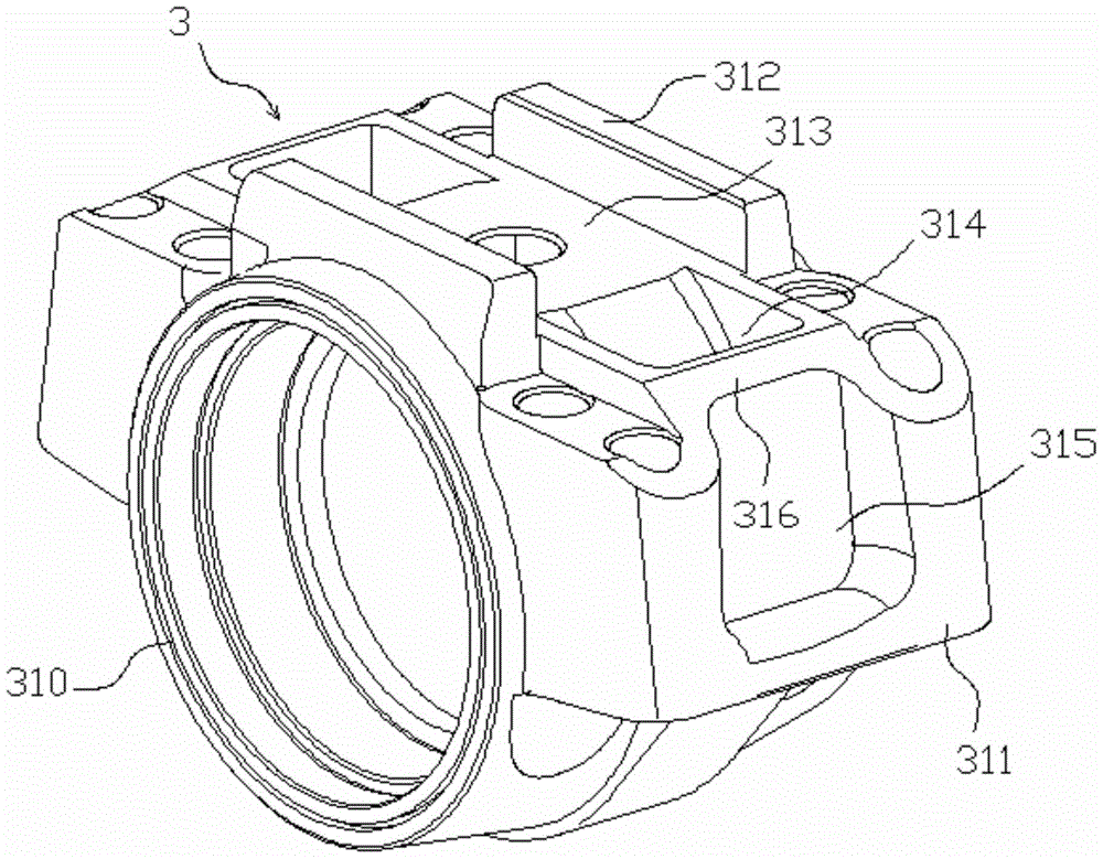
[0026] In order to further describe the present invention, the present invention will be further described in detail below in conjunction with the accompanying drawings and embodiments. figure 1 and 2 As shown in a heavy-duty balance shaft assembly, the two sides of the shaft 5 are supported by the shaft bracket 4, the end of the shaft 5 is arranged in the shaft housing 3 through the bearing, and the end of the shaft housing 3 is provided with an end cover 411, and the shaft The top of the belt bracket 4 is L-shaped, and it has two mounting surfaces matched with the vehicle frame 1. The upper parts of the two shaft belt brackets 4 are connected by an upper connecting plate 6, and the middle part of the upper connecting plate 6 is provided with a square hole 61. The bottom of each shaft belt bracket 4 is connected by the lower connecting plate 9, the lower connecting plate 9 consists of a sloping plate portion 91 and straight plate portions 92 placed on both sides of the slopin...


PUM


Abstract

The invention relates to the technical field of automotive part processing, in particular to a heavy-load balance shaft assembly. The upper portions of two shaft brackets are connected through an upper junction plate, a square hole groove is formed in the middle of the upper junction plate, the lower portions of the two shaft brackets are connected through an lower junction plate, the lower junction plate is composed of an inclined plate part and straight plate parts arranged on two sides of the inclined plate part, and a certain inclined angle between the inclined plate part and the straight plate parts is formed. A closed frame is defined by the two junction plates and is formed in the balance shaft assembly, local stress conducted on the frame is transferred and dispersed through the two junction plates, the brackets are protected, the danger that the brackets are fractured due to the fact that the local stress conducted on the brackets is too large is lowered, and the maintenance service cost is lowered. The lower junction plate adopts a bending and inclining design, the connection strength is guaranteed, meanwhile an envelope area of a transmission shaft can be kept off furthest under limiting conditions, it is guaranteed that the lower junction plate can not intervene the transmission shaft, and the lower junction plate cannot scrape the ground due to the fact that the lower junction plate is too near to the ground.

Description

technical field [0001] The invention relates to the technical field of vehicle parts processing, in particular to a heavy-duty balance shaft assembly. Background technique [0002] In recent years, my country's economy has been booming. As a means of production, heavy trucks are tools for users to survive and get rich, and have broad market prospects. At present, the demand trend of the heavy truck market is to develop towards large and heavy trucks, and its safety, reliability, and economy are particularly important. At the same time, the requirements for the technical level and service level of manufacturers are higher. However, most balance shaft manufacturers have been plagued by claims and high service fees, and the after-sales service of balance shaft assemblies in mining areas is particularly difficult. Most of the reasons are analyzed due to overloading, which makes it difficult for the balance shaft assembly to withstand the overloaded load, serious bearing wear, b...

Claims


Application Information

Patent Timeline
Patent Type & Authority Patents(China)
IPC IPC(8): B60G21/04B60G11/02B60B35/16
Inventor 李婷婷刘言言唐晓兵于洪涛张松
Owner ANHUI ANKAI JINDA MACHINERY MFG
Learn More