Eureka AIR delivers breakthrough ideas for toughest innovation challenges, trusted by R&D personnel around the world.

Production line vehicle accumulation battery installation device

A technology for installing devices and batteries, which is applied to electric power units, power units, vehicle components, etc., can solve the problems of high labor intensity, low labor intensity, and missing batteries for operators, so as to solve the problems of missing batteries and reduce labor intensity. , the effect of improving production efficiency

Active Publication Date: 2015-07-01
ZHEJIANG GEELY HLDG GRP CO LTD +1
View PDF7 Cites 3 Cited by
  • Summary
  • Abstract
  • Description
  • Claims
  • Application Information

AI Technical Summary

Problems solved by technology

[0005] The purpose of the present invention is to overcome the battery installation in the vehicle production line in the prior art. The manual installation of the operator not only causes the operator's labor intensity to be high and is easy to fatigue; To solve the problem of battery installation, it provides an assembly line vehicle battery installation that not only has low labor intensity, but also reduces the number of assembly line operators, improves the degree of automation of the assembly line, and improves production efficiency; and effectively solves the problem of missing batteries due to the negligence of operators. device

Method used


Image

  • Production line vehicle accumulation battery installation device
  • Production line vehicle accumulation battery installation device
  • Production line vehicle accumulation battery installation device

Examples


Embodiment Construction

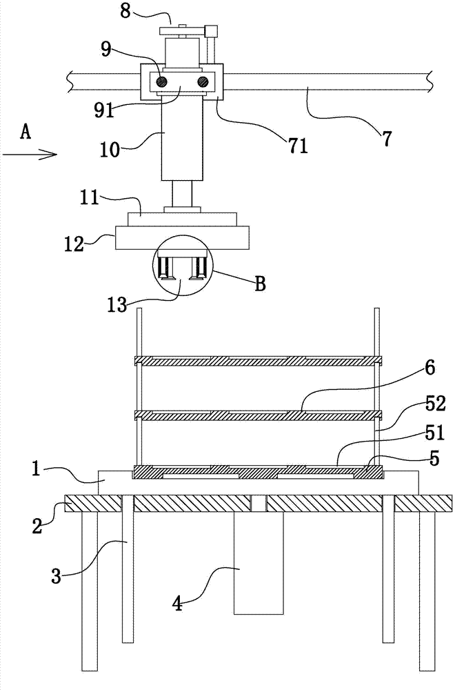
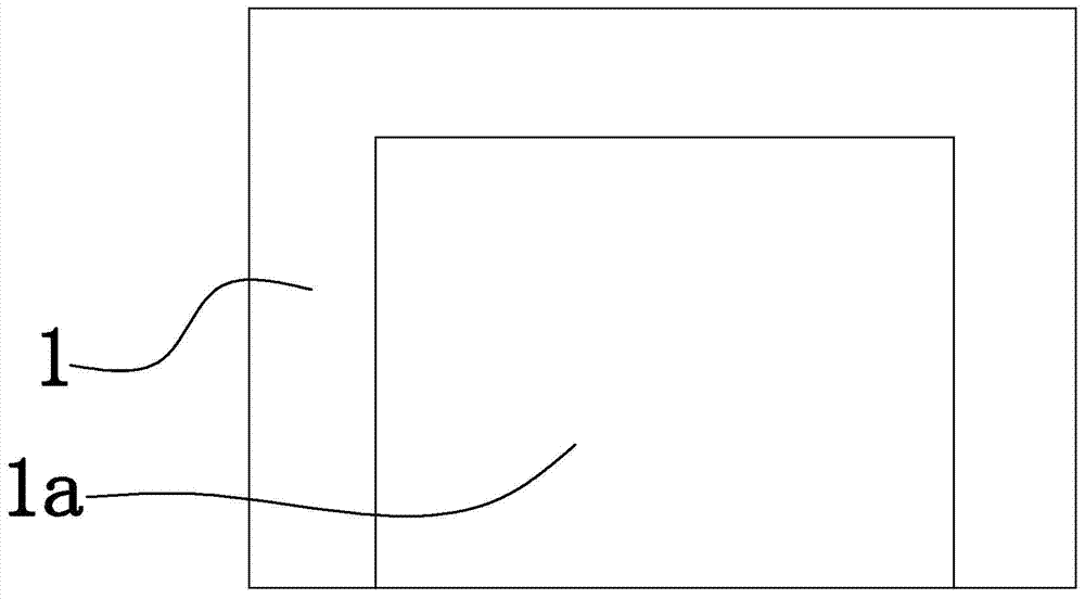
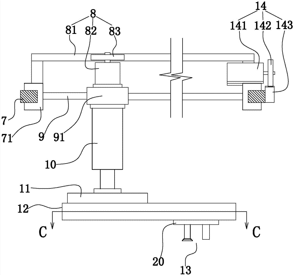
[0028] Below in conjunction with accompanying drawing and specific embodiment the present invention is described in further detail:

[0029] Such as figure 1 , figure 2 , image 3 As shown, an assembly line vehicle battery installation device includes a support plate 2, a plurality of partitions 6, a bracket 1, a tray limit groove 1a arranged on the top surface of the bracket, and a tray 5 arranged in the tray limit groove; The transverse guide rail 7 above the bracket can slide the transverse slider 71 arranged on the transverse guide rail, and is used to drive the transverse movement actuator 14 that the transverse slider moves along the transverse guide rail; the longitudinal guide rail 9 arranged on the transverse slider can Sliding the longitudinal slider 91 arranged on the longitudinal guide rail is used to drive the longitudinal movement actuator 8 that the longitudinal slider moves along the longitudinal guide rail; the mounting seat 11 arranged under the longitudin...


PUM


Abstract

The invention discloses a production line vehicle accumulation battery installation device which can effectively lower labor intensity, reduce the number of operators for a production line and improve the degree of automation of the production line. The production line vehicle accumulation battery installation device comprises a bracket, a pallet limiting groove, a pallet, a transverse guide rail, transverse sliding blocks, a transverse moving execution device, a longitudinal guide rail, a longitudinal sliding block, a longitudinal moving execution device, an installation base, a first lifting execution device and a clamping positioning device, wherein the pallet limiting groove is formed in the top surface of the bracket, and the pallet is arranged in the pallet limiting groove; the transverse guide rail is arranged above the bracket, the transverse sliding blocks are arranged on the transverse guide rail in a slideable mode, and the transverse moving execution device is used for driving the transverse sliding blocks to move along the transverse guide rail; the longitudinal guide rail is arranged on the transverse sliding blocks, the longitudinal sliding block is arranged on the longitudinal guide rail in a slideable mode, and the longitudinal moving execution device is used for driving the longitudinal sliding block to move along the longitudinal guide rail; the installation base is arranged below the longitudinal sliding block, the first lifting execution device is arranged on the longitudinal sliding block and used for driving the installation base to lift vertically, and the clamping positioning device is arranged on the installation base.

Description

technical field [0001] The invention relates to an installation device, in particular to an assembly line vehicle battery installation device. Background technique [0002] With the continuous development of the automobile industry, the degree of mechanization in the automobile manufacturing process is getting higher and higher; the application of some semi-automatic and fully automatic equipment not only reduces the labor intensity of workers; but also greatly improves the production efficiency of vehicles, better However, at present, on the vehicle production line of domestically produced vehicles, the installation of the battery in the engine compartment of the vehicle mainly depends on the manual installation of the operator. [0003] At present, the battery installation process on the vehicle production line is usually as follows: when the vehicle on the assembly line is at the battery installation station, the operator removes the battery from the pallet; then, the ope...

Claims


Application Information

Patent Timeline
Patent Type & Authority Applications(China)
IPC IPC(8): B60K1/04
Inventor 李书涛顾伟明
Owner ZHEJIANG GEELY HLDG GRP CO LTD
Why Eureka
Eureka Blog
Learn More